prestonee
Full Member level 3
- Joined
- Jan 9, 2013
- Messages
- 177
- Helped
- 45
- Reputation
- 94
- Reaction score
- 45
- Trophy points
- 1,308
- Location
- United States
- Activity points
- 2,713
I am seeking to better understand the reduction of circuitry to simplify noise calculations.
for example vnoise of resistor is sqrt(4ktr), and total noise of a resistor with a cap to ground is sqrt(kt/c) all good and dandy with the basics.( i hate relying on memorizing such answers since this can get you in trouble so i like to be able to hand check. in this case I do vin^2=4ktr, and vo^/vi^2= ((1/sc)/(r+1/sc))^2= 1/(scr+1)^2, to get vo^2=4ktr/(scr+1)^2 = 4ktr* 1/(1+j*2*pi*f*c*r)^2, take the abs to remove the i gets you to 4ktr* 1/(sqrt(1+4*pi^2*f^2*c^2*r^2))^2 which finally ends in 4ktr*1/(1+4*pi^2*f^2*c^2*r^2), integrate over freq and you get 4*k*t*r * pi/(2*2*pi*c*r) = k*t/c .
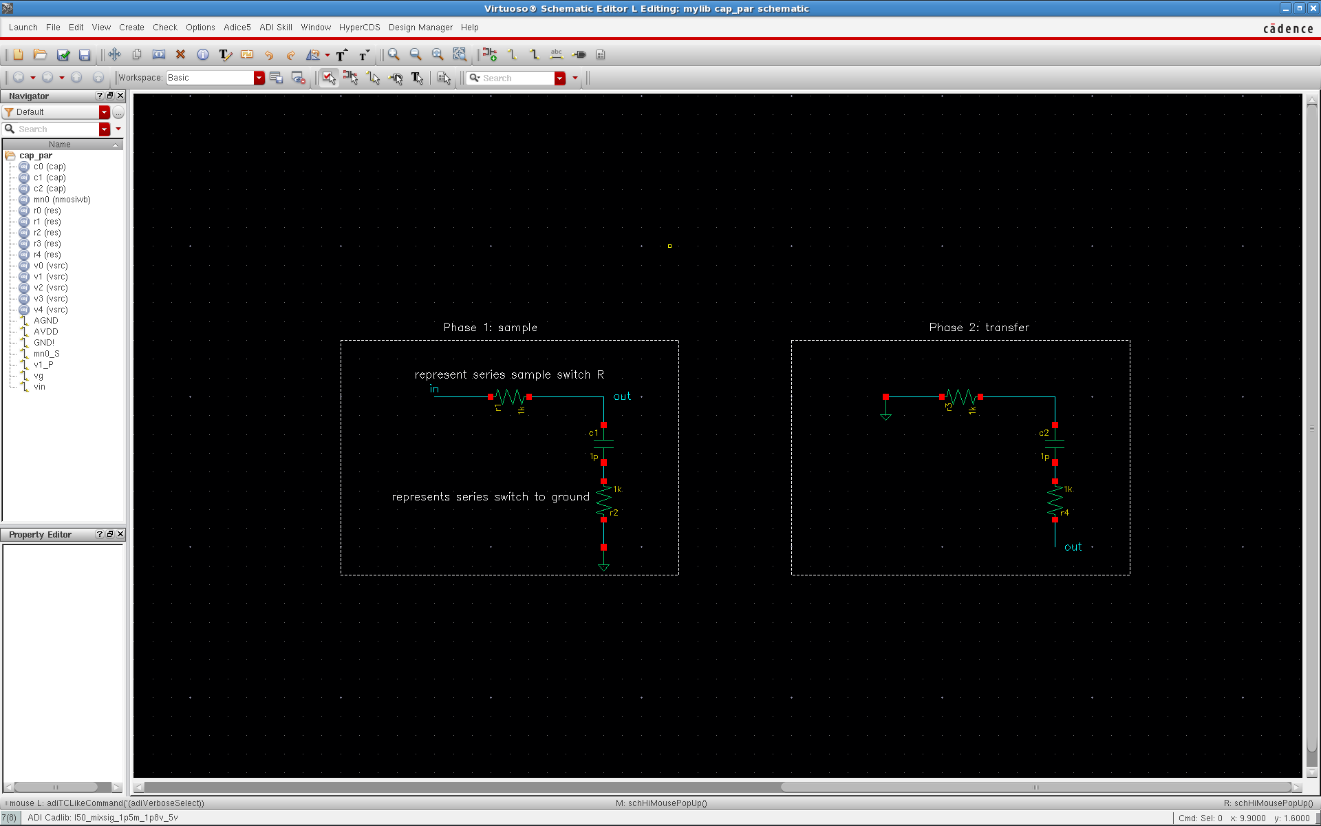
as you see solving a simple rc is a bit of work, but then if you add a resistor on the other side of the cap, rcr. it gets nasty quick(solving the system twice using superposition for the two res noise sources, and the integral is much nastier and hard to do). But I have seen where people take a rcr, and magically flip the bottom r to the top and solve as a rc with r =sum of two r's. and the circuits i try to solve are much more complex with multiple r's and c's and while simulation can give me a value I wish more to be able to see the relationship of noise sources to the overall noise sum. how can rc noise sources be reduced? if you have a res in series with a cap in series with a res to ground, how can you simplify this to a single r, where one noise source has a rc filter impact and the other source must travel through the c, effectively making one noise source low pass filtered and the 2nd noise source highpass filtered? someone in person spoke to me about in a switch cap circuit its the noise being sampled on the cap that matters, but converting the switch to its on res and solving as above i believe is equivalent. however when the noise is being transferred to the next circuit that same res impacts the noise still, so it must be included in both calculations, calculating the voltage noise stored on the cap, and while at it the non ideal switch on the other end of the cap is connected to ground making the rcr i was referring to, this r contributes as well because it effectively is randomizing an offset ontop of the ideal ground that the voltage is in respect to. then when the voltage on the cap is used in the next phase the resistor on the ground side of the cap is still impacting the voltage while the new switch in r for phase 2 is also being added.....so to me even a simple switch cap when you account for the nonideal switching r's and both phases it gets very complex to calculate one simple circuit...
please help me out of the black cave ...
-Preston
for example vnoise of resistor is sqrt(4ktr), and total noise of a resistor with a cap to ground is sqrt(kt/c) all good and dandy with the basics.( i hate relying on memorizing such answers since this can get you in trouble so i like to be able to hand check. in this case I do vin^2=4ktr, and vo^/vi^2= ((1/sc)/(r+1/sc))^2= 1/(scr+1)^2, to get vo^2=4ktr/(scr+1)^2 = 4ktr* 1/(1+j*2*pi*f*c*r)^2, take the abs to remove the i gets you to 4ktr* 1/(sqrt(1+4*pi^2*f^2*c^2*r^2))^2 which finally ends in 4ktr*1/(1+4*pi^2*f^2*c^2*r^2), integrate over freq and you get 4*k*t*r * pi/(2*2*pi*c*r) = k*t/c .
as you see solving a simple rc is a bit of work, but then if you add a resistor on the other side of the cap, rcr. it gets nasty quick(solving the system twice using superposition for the two res noise sources, and the integral is much nastier and hard to do). But I have seen where people take a rcr, and magically flip the bottom r to the top and solve as a rc with r =sum of two r's. and the circuits i try to solve are much more complex with multiple r's and c's and while simulation can give me a value I wish more to be able to see the relationship of noise sources to the overall noise sum. how can rc noise sources be reduced? if you have a res in series with a cap in series with a res to ground, how can you simplify this to a single r, where one noise source has a rc filter impact and the other source must travel through the c, effectively making one noise source low pass filtered and the 2nd noise source highpass filtered? someone in person spoke to me about in a switch cap circuit its the noise being sampled on the cap that matters, but converting the switch to its on res and solving as above i believe is equivalent. however when the noise is being transferred to the next circuit that same res impacts the noise still, so it must be included in both calculations, calculating the voltage noise stored on the cap, and while at it the non ideal switch on the other end of the cap is connected to ground making the rcr i was referring to, this r contributes as well because it effectively is randomizing an offset ontop of the ideal ground that the voltage is in respect to. then when the voltage on the cap is used in the next phase the resistor on the ground side of the cap is still impacting the voltage while the new switch in r for phase 2 is also being added.....so to me even a simple switch cap when you account for the nonideal switching r's and both phases it gets very complex to calculate one simple circuit...
please help me out of the black cave ...
-Preston
Last edited:
")