Continue to Site

Welcome to EDAboard.com

Welcome to our site! EDAboard.com is an international Electronics Discussion Forum focused on EDA software, circuits, schematics, books, theory, papers, asic, pld, 8051, DSP, Network, RF, Analog Design, PCB, Service Manuals... and a whole lot more! To participate you need to register. Registration is free. Click here to register now.

Newbie question: Passive Delay Circuits

Status
Not open for further replies.

SparkyNZ

Newbie level 5
Joined
Dec 1, 2011
Messages
9
Helped
0
Reputation
0
Reaction score
0
Trophy points
1,281
Activity points
1,367
Hi, I'm somewhat inexperienced in electronics (I've soldered wires, cables, made a few circuits with 555 timers etc). I have an old vintage computer that I've just rewired to with with S-video.

The problem I have is that the luminance and chromaticity signals are slightly out of phase which results in a little ghosting on my monitor.

Could somebody please recommend a way in which I could build a circuit that would introduce a delay of around 150 nanoseconds on the signal? I'd want to be able to try adjust the delay slightly too.

I've been recommended a TZB78-7 IC form Rhombus but quite simply because I only would want one chip, they're not interested in me making an order.. so I'm wondering if there's a low cost way of building such a circuit from good old-fashioned everyday components?

Thanks
Paul
 

As the datsheet reveals, the said "IC" is containing nothing but a LC delay line. Of course you can assemble it from discrete inductors and capacitors as well.
 

As the datsheet reveals, the said "IC" is containing nothing but a LC delay line. Of course you can assemble it from discrete inductors and capacitors as well.

Thanks for having look. Do you know what value of L and C I'd need? If I wanted to vary the delay from say 100ns through 200ns, which component would I need to buy as a variable? Can you buy variable inductors?? From memory you can buy variable capacitors as thats what you have in a radio tuner, yes? I think I need to maintain 75 Ohm impedance.. not too sure where that comes in? Sorry.. I'm more of a digital electronics person that analogue. :)
 

You can refer to the simple transmission line LC equivalent circuit and implement it as a tapped 10 element LC chain similar to the retail component. Using less than 10 LC elements is possible, but reduces the cut-off frequency.

Z = √(L/C), TD = √(L*C)

P.S.: You get 1.5 uH + 270 pF for a 20 ns 75 ohm element, which are reasonable values for discrete chips. The end capacitors should be about half the value.
 
Last edited:
Using less than 10 LC elements is possible, but reduces the cut-off frequency.

Z = √(L/C), TD = √(L*C)

P.S.: You get 1.5 uH + 270 pF for a 20 ns 75 ohm element, which are reasonable values for discrete chips. The end capacitors should be about half the value.

If I use 10 pairs of components, is it just a matter or putting the 10 components in series? In an DC circuit I would expect the resistance to become 750 ohms.. In an AC circuit will the impedance remain at 75 ohms if 10 pairs are used in a series chain? Thanks

Update: Our one and only component shop doesn't sell inductors as low as 1.5uH (47uH and 100uH are the lowest values). What would be the best way to get around this? Can you use inductors in parallel to lower the value similar to resistors in parallel? If not and I have to increase the inductance, that will need a smaller capacitor (e.g. 27pF). Will a smaller capacitor work OK the same or will that introduce filtering effects?
 
Last edited:

Z = √(L/C) is similar to a transmission line characteristic impedance. It has to be kept on in- and output to achieve impedance matching and maximum signal transmission. Calculation rules are quire different from DC circuits.
 
Color tv's used a length of wire 150 feet long (wrapped in a coil), to create a delay in order to align chroma and luminance signals.

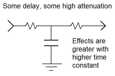
A capacitor can introduce a delay by hooking it up in the same way you would use it to divert high frequencies. The delay is different at different frequencies.

A coil in series would act the same way. Low pass and some lag.

23_1322847022.gif


The result may or may not be satisfactory. There may be loss of clarity (smear).

To obtain a time constant of 150 nSec, you must choose the right value capacitor based on surrounding impedance. The formula for time consant is TC=Resistance x Capacitance.

Try cap values in the 10 pF to 1000 pF range.
 
Thanks Brad. I bought some 1.5uH chokes (hope these are truly inductors!) and 270pF capacitors yesterday. (11 of each). I worked out the time delay as being 20ns for a pair of each.. so I should be able to create a delay of 180-220ns in theory. I haven't had a chance to try them out yet and today is looking busy too. :(

I reckon I'm going to need a variable capacitor of some sort to fine tune my circuit but at the moment I just want to prove to myself the ghosting will lessen (or increase) when I put the circuit into either the chroma or luminance signal.
 

This is not exactly the same as what you're doing, but the following web page (or similar) showed me how to make my own cable for converting S-video (Y/C video) to composite (phono-plug).

It uses a 470 pF capacitor in the line labelled 'C'.

The adapter gives good results when watching Youtube videos. However a CRT television makes a blurry computer display, so it is not usable to see detail. An led screen will be more detailed but it will show ghosting better too.

S-video to composite video

The article mentions a luma trap IC, AD725.
 
Thats pretty useful, Brad. I need to solve the ghosting for an NTSC and PAL machine so I'm going to make a shielded box that will handle the two different delays. Just need to buy some S-video male/female plugs first before I go ahead and give it a go. I'll report back with the results (or questions!) once I give it a go this week. Cheers.
 

Did you check as to what number of pins is on the S-video connector on your equipment? There's a 4 pin type and there's a 7 pin type.

The 4-pin type carries video only. The 7 pin type may or may not contain audio.
 

Did you check as to what number of pins is on the S-video connector on your equipment? The 7 pin type may or may not contain audio.

Yeah I made the cable previously. The Audio goes down seperate cables into RCA connectors so its definitely a 4 pin S-video cable. The computer (and old Commodore Vic20) never had S-video previously. I made a modification to the motherboard to get the seperate chroma and luma signals and installed an S-video socket on the back of the machine. No kids tonight so I should be able to give it a try! :) Its finding the window of opportunity that is the greatest challenge! (And juggling other projects too I suppose :) )
 

I still have my VIC20. Haven't turned it on in a while.

Guess I'm sentimental so I hang onto it. Or else I'm hoping it will be worth a lot of money someday.

I did a mod to its video cable so I could feed it directly to the video input on a tv, thus getting a clearer image, rather than having to use the rf modulator.
 

Hi. I've given up. No matter what combination of things I've tried tonight, I simply cannot get rid of the dark lines on the edges of pixels. I managed to introduce "white" ghosting in various amounts but I cannot get rid of these dark edges. I tried putting the delay circuit on both chroma and luma lines but no luck.

Here's a picture of how my Vic looks without any delay mods:

119mskg.jpg


Perhaps I am just expecting too much out of the S-video signal.. My C64C is about the same too and I've tried 2 different TVs and different cables.

Cheers
Paul
 

A luminance to chrominance delay difference would show in asymmetrical patterns (left edge different from right edge). I almost don't see it in your picture, thus unless you have contradicting observations, there's no delay problem, I think.
 

Yeah I only have an iPod for taking pictures. On some of the blue characters I can see pink/purple ghosts of the characters to the left and the blue pixels have dark edges on them (same sort of 'spill' that you can see on the left of the screen). Given that I have introduced 'white' ghosting in both directions I would agree with the delay not being the problem. If I turn the sharpness setting right down on the TV, the problem goes away but then the pixels become blurred.

I also noticed by accident that when I only had the luminance line connected, I could stilll see subtle colours on the 'black and white' display. The image is very sharp without colour.. so I may tweak the Vic pots and see if turning down the colour saturation helps in some way.
 

By design of the TV standards relying on modulation of the color information, the bandwidth respectively detail resolution of the chrominance channel is only a fraction of the luminance channel. That's the basic problem. You also can't avoid some pulse distortion effects that can't be easily distinguished from delay differences.

I assume, that a small improvement of picture quality can be achieved by adjusting the C-to-Y delay carefully, but most effects are most likely of different kind.
 

Your pic shows as beautiful an image as I ever got with my VIC20 or C-64. On a tv or a monitor.

I say beautiful because I remember having to put up with rf herringbone interference for years. Until I got a 1701 Commodore monitor. It made about as nice an image as you posted.

The coloring was always off (especially yellow) when using a tv. It would require that I fine tune the tint control. Later everything was the wrong color when I went back to watching tv programs.

Notice there is an artifact BOTH when the electron gun switches from dark to light, AND light to dark. Chiefly when looking at the color bars. This is because it's a severe change to transition from dark to light (or vice versa). Consider that it has to take place in a microsecond.

So it's not surprising there will be some artifacts at the transitions.

Notice there is no ghosting at the border of colors when there is not so much contrast of the colors.

It really takes a computer monitor to make the sudden high-contrast transitions as crisply as a computer requires. That must be why a monitor used to cost several times the cost of a tv.
 
Last edited:

Your pic shows as beautiful an image as I ever got with my VIC20 or C-64. On a tv or a monitor.
I say beautiful because I remember having to put up with rf herringbone interference for years. Until I got a 1701 Commodore monitor. It made about as nice an image as you posted.

It is certainly way better than I ever remember. I think I'm just spoiled with expectation after using the VICE emulator and typical PC displays. The image I get on my plasma TV is severely ghosted - far worse than this image which was from a small LCD TV.

I might try one of those S-video to VGA boxes out as well. They're pretty cheap.. I have an AverMedia video converter and took some video with that. Perfect images all round but of course that requires a PC running that device as well. :)
 

Status
Not open for further replies.

Similar threads

Part and Inventory Search

Welcome to EDABoard.com

Sponsor

Back
Top