Continue to Site

Welcome to EDAboard.com

Welcome to our site! EDAboard.com is an international Electronics Discussion Forum focused on EDA software, circuits, schematics, books, theory, papers, asic, pld, 8051, DSP, Network, RF, Analog Design, PCB, Service Manuals... and a whole lot more! To participate you need to register. Registration is free. Click here to register now.

Newbie needs some help

Status
Not open for further replies.

Garry34

Newbie level 3
Joined
Jun 19, 2011
Messages
3
Helped
0
Reputation
0
Reaction score
0
Trophy points
1,281
Location
Upwey, Victoria, Australia
Activity points
1,315
Howdy guys,

I am not sure I am doing this correctly, in the right place, or even if my question is dumb, but here is my problem. I work part-time travelling to schools doing lectures on the archaeology and history of the ancient world; I transport a travelling exhibition of artefacts, replicas, and models with me.

I am building a new archaeological showcase to take to schools and in it is a sculpted 3D model of the Valley of the Kings in Egypt. At the location of each Egyptian tomb is a red LED.

My idea is this: using a 9V battery and a row of press-button switches each labelled with the name of an individual (Pharaoh or other individual) buried in the Valley of the Kings, I wish students to be able to press a switch and the appropriate LED to light up for say 20 seconds or so and then switch OFF.

If another button is pressed while any LED is ON it should switch the lit LED OFF immediately and the new LED light up with the timing restarting. The CCT should draw minimal (or preferably zero) current when all LEDs are OFF to conserve battery power supplied by a 9V battery. How can I do this with a minimum of components and minimum current drain?

Perhaps one of you guys could propose a CCT for my addled brain? There are 36 LEDs on the model.

Thank you,

Garry
 

What you are asking for is an exclusive latch, one that updates with each new key press and releases any previous selection.
There are several ways to do this, the classic method is to use 8-bit static latches but you would need five of them and some extra circuitry to create the 'release' signal and turn off delay. You would likely have a circuit board with as many as 10 ICs on it.
The alternative is to use a microprocessor and multiplex the LEDs. This might drop the IC count down to just one and very considerably reduce the amount of wiring but you would have to write some relatively simple software to operate it. The multiplexing principle relies on persistence of vision, you pulse the LEDs very quickly rather than leaving them on the whole 20 seconds, because we can not see flashes faster than about 50 per second, the LED appears to be on all the time. Although it sounds a bit complicated, it actually makes a much simpler design and the person viewing it sees exactly as they would with the 10 IC solution.

Brian.
 

:-D
And just to illustrate how complex may be a schematics using standard ICs, here's a demo version that uses five MC14508 and one CD4093 circuit.
 

Attachments

  • LATCH Circuits.JPG
    LATCH Circuits.JPG
    182.9 KB · Views: 85
Last edited:

I got an idea , here is the principle ............

If someone has time to check and simulate, is this working circuit , so please do it.

N_Leds_Sw_Delay_01.jpg

KAK
 

Easiest is to use a micro controller. Arrange the LEDs in a 6 x 6 matrix and also connect the drive signals to a matrix of keys. That gives you 36 switches, 36 LEDs and only 18 connections to the processor. The 20 second delay can easily be created in software. It's much easier to wire up 18 connections than the 74 demonstrated in mister_rf's example!


Brian.
 

Thanks Betwixt,

I had thought of programming a microprocessor to do this, but my knowledge is very rusty!

Thank you

Garry34

---------- Post added at 12:04 ---------- Previous post was at 12:03 ----------

Thank you kak111,

I will give this a go and let you know.

Thanks again sir,

Garry34

---------- Post added at 12:08 ---------- Previous post was at 12:04 ----------

Thank you mister_rf,

You have just scared the daylights out of me!

Thanks,

Garry34
 

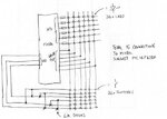
Putting the problem in perspective, I've attached the multiplexed solution. This would include the timer which is not included in the design shown by mister_rf.
Sorry for the horrible quality, I scribbled it on a bumpy train journey. The micro could be a PIc16F628A which costs peanuts.

Brian.

key_leds.jpg
 

By the way, the idea was to create some sort of timer using a gates and capacitors. :grin:
Pressing any button will put MR on low (charging C1), activating all the circuits, later on the strobe signal charge the data level to high on the specified output and maintain all circuits activated for additional 20-30s until the capacitor C1 is discharged.
Anyway, the ‘’demo’’ circuit has some errors :roll: , the LEDs need to be on reverse, 14508 put level high on selected output, and a GND instead Vcc to be used.
 

Attachments

  • timings.GIF
    timings.GIF
    5.3 KB · Views: 66
Last edited:
Putting the problem in perspective, I've attached the multiplexed solution. This would include the timer which is not included in the design shown by mister_rf.
Sorry for the horrible quality, I scribbled it on a bumpy train journey. The micro could be a PIc16F628A which costs peanuts.

Brian.

View attachment 57475

Thanks Brian,

Do you remember the old Goon Gag:

Neddy Seagoon: "My name is Neddy and I come from Wales!"
Eccels: "Well it's easy to see you don't come from sardines mate!"

Many thanks.

---------- Post added at 19:10 ---------- Previous post was at 19:08 ----------

Thanks again mister_rf!

Garry34
 

Status
Not open for further replies.

Part and Inventory Search

Welcome to EDABoard.com

Sponsor

Back
Top