Continue to Site

Welcome to EDAboard.com

Welcome to our site! EDAboard.com is an international Electronics Discussion Forum focused on EDA software, circuits, schematics, books, theory, papers, asic, pld, 8051, DSP, Network, RF, Analog Design, PCB, Service Manuals... and a whole lot more! To participate you need to register. Registration is free. Click here to register now.

Newbei: power divider for 20 Ghz local oscilator. Help???

Status
Not open for further replies.
Dear sir, thats exactly what i did, i have used the LineCalc to find the length and width of the microstrip lines for 50 ohm and for 70.07 ohm. i keep the 50 ohm lines constant and the resister is fixed. i am only varying the length and width of the quarter wave line.the width of the Mbend is kept the same as width of quarterwave line.
the online thing i dont know waht effect it could bring is the microstrip line from between Tee's used to connect the resistor...
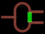
my schematic and layout looks as follow.
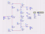
Power Divider1.PNG
Power Divider2.PNG

but unfortunately i am unable to tune this circuit for 20 Ghz, i also set optimization Goals but even they did not provide some good results.
there come a clash between schematic and layout design. some time when schematic gives good results, the length and width of lines are often annoying, sometimes they overlap bcoz of extra length or sometimes bcoz of short length, there is a big gap even to set the resister to its place...

i know that the variation in length and width of quaterwave can hit the spot but the thing annoying me is even this thing does'nt helps...

:( :(
 

Attachments

  • Power Divider1.bmp
    2.7 MB · Views: 51
  • Power Divider2.bmp
    2.6 MB · Views: 48

It looks like you have a decent schematic to drive a layout that might get you where you want to go. The problem at this stage of the design process is that the optimal schematic design and optimal layout/EM design are not very similar to one another.

I do have a couple things that you should update/verify before getting too far along.

1. Remove the MSTEP and MLINs between the resistor ports and the MTEEs, they really don't serve a purpose. To compensate the variation in the Y direction, change the lengths of TL8 and TL9. Notice the symmetry (draw a line down the X-axis, and it should be a mirror image. If you add up the length of the resistor (divided by 2), plus the height of Tee17, it should be equal to (1/2 of W3 of Tee20)+Length of TL9. This will ensure that the 180 degree curve starts and ends at the same height on the Y-axis.

2. Change Rs of the resistor to 50 ohms/square. Rs is the sheet resistance. Thin-film resistor value, R = Rs*Length/Width. So, to get a 100 ohm resistor...
100 = 50*(2/1), which you pretty much have... L=1.52, W=0.762. R = 50*(1.52/0.762) = 99.7 ohms (good enough). To better envision how thin-film resistor work, cut the material into squares. Each square is like a single resistor with a value of Rs. If you have a long, narrow resistor between two metal contacts, then you have two squares "in series", so R = Rs + Rs +...

If you have a short, wide strip of thin-film resistor between your contacts, that will act like several Rs resistors connected in parallel. If the aspect ratio of the patch is L=1, W=4, then R = (1/50 +1/50 +1/50 +1/50)^-1 = 12.5 ohms.

3. Rather than always tuning the width of your 50 ohm lines and Tees, fix those values to keep you from confusing them. The only parameters you should need to tune are the length of Curve11 & 12, and their width (and the associated widths of Tee16, 17, 20 and TL8 and 9).

4. Ensure that you are setting up the thin-film resistor in the Momentum stack-up editor correctly. It should be added as a Strip on the same later as Cond. The material type should be Impedance, and then you enter the sheet resistance of 50 ohms/sq.

A quick way to check your setup is to make a square resistor and put two short 50 ohm microstrip lines on each port. When you simulate this, it should look like a voltage divider with two 50 ohm resistors (one resistor is the thin-film resistor, the second resistor is the 50 ohm load presented by the port). So, your output voltage will be 1/2 the input voltage, and S21 = 20*log(V2/V1), so S21 should be -6 dB.

5. Reduce the length of your resistor. Right now it's 1.52mm long. Using Er = 3.38, I get Ee = 2.67, which makes one wavelength = 9.2mm. 1.52 / 9.2 * 360 = 60 degrees long. That's far too long, electrically. You want the resistor to be electrically very, very short... like less than 5 degrees. You may need to choose a different substrate, something with a MUCH higher Er. For the design I recently did @ K-band, I was using 10 mil thick Alumina, which has and Er around 9.8. I'd suggest going up to that range, so you can shrink your overall artwork size to a smaller fraction of a wavelength. Maybe look at Rogers 3010, 3210, TMM10, TMM10I. I'm not sure about printing thin-films on PTFE-like dielectric boards, that may not be possible, so you may have to look at something like Alumina.
 

Have you tried ADS Design Guide? It is better to design initial circuit using ADS Design guide then optimize it. It will not only help you in getting better design but also in proper layout.
Please check your 'ARC Resolution'. It must be less than 20 for proper results.
 

A quick way to check your setup is to make a square resistor and put two short 50 ohm microstrip lines on each port. When you simulate this, it should look like a voltage divider with two 50 ohm resistors (one resistor is the thin-film resistor, the second resistor is the 50 ohm load presented by the port). So, your output voltage will be 1/2 the input voltage, and S21 = 20*log(V2/V1), so S21 should be -6 dB.

5. Reduce the length of your resistor. Right now it's 1.52mm long. Using Er = 3.38, I get Ee = 2.67, which makes one wavelength = 9.2mm. 1.52 / 9.2 * 360 = 60 degrees long. That's far too long, electrically. You want the resistor to be electrically very, very short... like less than 5 degrees. You may need to choose a different substrate, something with a MUCH higher Er. For the design I recently did @ K-band, I was using 10 mil thick Alumina, which has and Er around 9.8. I'd suggest going up to that range, so you can shrink your overall artwork size to a smaller fraction of a wavelength. Maybe look at Rogers 3010, 3210, TMM10, TMM10I. I'm not sure about printing thin-films on PTFE-like dielectric boards, that may not be possible, so you may have to look at something like Alumina.

1.Can you please explain a little bit the realtion b/w Er, Electrical length and Wave length. (sorry for my bad knowledge, what does Ee and ' electrical length in degrees 'means, what are the optimal values for 20 GHz)
2. I do not get how 'to make a square resistor' do u mean, instead of resister i put 2 short 50 ohm lines whose sum up length is equal to the length resistor.
3. the problem is about substrate is that from my deparment side i asked for Alumina and they rejected my request bcoz of low bugget and high amount of RO4003C availability.
4. the biggest problem i am facing is even my supervisor doesn't know which resistor to be used for 20 Ghz (they always ask me to use one of the available from the Lab i.e 0402 or 0603), and since in case i can not fix the resistor size, its difficult for me to adjust the quater wave transformer length/width.

one of my friend suggest that because of design complixity, I don't go for a wilkinson divider but may be a simple microstip divider in CST, do u think it would work or shall i stick to wilkinson power divider.
 

Status
Not open for further replies.

Similar threads

Part and Inventory Search

Welcome to EDABoard.com

Sponsor

Back
Top