Continue to Site

Welcome to EDAboard.com

Welcome to our site! EDAboard.com is an international Electronics Discussion Forum focused on EDA software, circuits, schematics, books, theory, papers, asic, pld, 8051, DSP, Network, RF, Analog Design, PCB, Service Manuals... and a whole lot more! To participate you need to register. Registration is free. Click here to register now.

[SOLVED] Negative 12v (-12v) from +12v ?

Status
Not open for further replies.

kripacharya

Banned
Advanced Member level 4
Joined
Dec 28, 2012
Messages
1,204
Helped
182
Reputation
360
Reaction score
175
Trophy points
1,343
Location
New Delhi
Visit site
Activity points
0
Here's the specs :

Input is +12v capable of upto ~1amp.
output -12v (upto -12.8v) (not -10v or -11v or anything else) with atleast 60mA.

Should NOT use any of the myriad converter/ switch-mode chips.
Off-the-shelf junk-box chips & components are ok. E.g. 555, 2n7000, inductors, caps, zeners, opamps, comparators etc etc. Maybe even a small xfo, but avoid if possible.

design should be minimalistic & as simple as possible.

My thoughts were some form of Cuk circuit. But how to design it right ? Here's one i was playing with (its a LTSpiCE asc file. Rename it), but i don't like it.... :???:

Forums suggestions & guidance please ?
 

Attachments

  • negative voltage converter CUK.txt
    1.8 KB · Views: 1,425

A cuk converter is a very complicated and costly method relative to using a simple charge pump. What's wrong with using an off the shelf charge pump chip, like a TC962?
 

no chips please. Give me a 'discrete' design

- - - Updated - - -

no chips please. Give me a 'discrete' design
 

You could still use the charge pump method, just implement in discrete components (MOSFETs, diodes), and use a 555 to
operate it, although that's a chip (could be replaced with a discrete oscillator, depending on how far you want to go).
But, none of this is fun (including switching the MOSFETs without turning them both on at the same time).
It will be quite a large circuit overall - many discrete components.
 

design should be minimalistic & as simple as possible.
no chips please. Give me a 'discrete' design
Your demands are mutually exclusive. A "discrete" design with no specialized components will inherently have dozens of components. Simplest thing would probably be a buckboost converter using a P-FET, but it's still pretty complicated.
 

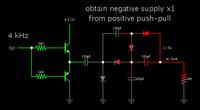
This arrangement will provide a negative supply from a positive push-pull, using a charge-pump.


Some kind of voltage multiplier has to be added. Without it the best you can get is -10.4V.

The clock pulses can come from a 555 IC (both source and sink current).

The supply draws 110 mA average. 316 mA peak.
 
A cuk converter is a very complicated and costly method

so did you have a look at my circuit ? Its not that costly if the parts come from my junk-box

relative to using a simple charge pump. What's wrong with using an off the shelf charge pump chip, like a TC962?

i'm happy to use a charge pump config, if it can give me -12v. There's nothing wrong with using TC962, just that i don't have one.

- - - Updated - - -

You could still use the charge pump method, just implement in discrete components (MOSFETs, diodes), and use a 555 to
operate it, although that's a chip (could be replaced with a discrete oscillator, depending on how far you want to go).
But, none of this is fun (including switching the MOSFETs without turning them both on at the same time).
It will be quite a large circuit overall - many discrete components.

sounds great. I can throw together oscillators in many ways - no probs. But the actual design of the charge pump stage which can deliver -12v @50mA is what i need.

- - - Updated - - -

Your demands are mutually exclusive. .

its not really a demand -- more like a design guideline.

- - - Updated - - -

This arrangement will provide a negative supply from a positive push-pull, using a charge-pump.

Some kind of voltage multiplier has to be added. Without it the best you can get is -10.4V.

The clock pulses can come from a 555 IC (both source and sink current).

The supply draws 110 mA average. 316 mA peak.

thats pretty cool Brad. I'll check it out. All the parameters seem to be met - except that the output is not controlled. Maybe just a 12v zener could do the job.

thanks !

- - - Updated - - -

You don't need any circuit for converting +12V to -12V, just interchange + and - terminals.......

no why didn't I think of that ?!?

- - - Updated - - -

So is the "no IC" a self-imposed requirement or a homework requirement?

did i write "no IC" ? I don't recall writing "no IC". The "no chips" comment was in response to a suggestion to use a specialised IC - TC962 - which i do not have.

- - - Updated - - -

So is the "no IC" a self-imposed requirement or a homework requirement?

well since my lab is in my home, i suppose it is both.
 

so did you have a look at my circuit ? Its not that costly if the parts come from my junk-box
......................
I ran the simulation and it did generate -12V but the zener diode shunt regulation is very inefficient. You have 50mA going through the load but almost 200mA going thorough the zener, dissipating over 2W in the zener.
 

I ran the simulation and it did generate -12V but the zener diode shunt regulation is very inefficient. You have 50mA going through the load but almost 200mA going thorough the zener, dissipating over 2W in the zener.

well yes, i said i didn't like it. That was a config thrown together to get a feel for the Cuk. No idea how to calculate/ design the actual component values .... yet.
Any pointers will be appreciated !!
 

The Cuk topology is quite complicated and would take many parts including some op amps to make. None of use really like to reinvent the wheel so just buy one of the ICs that do what you want. It's a lot easier and takes a lot fewer parts. ;-)
 

seriously ... no one knows how to design a Cuk topology converter ?

It is more efficient than the regular buckboost, but it is harder to build and get it to work successfully.

Here is a website which promotes the Cuk (boostbuck) converter:


The webpage talks about designing the transformer. There are several more pages. It offers a guide on how to make this type of converter (for $25.00).

thanks Brad, i already had a look at that website.
In the meantime found some very detailed analysis & design writeups, and spice simulations based on that are working great !! Exact same topology but components selected as per design, not random. And don't need that zener anymore. And getting upto 5x my target currents, with smaller components ... amazing.

Next step is to implement in real, with one finger on the MOSFET, another on the inductor, a 3rd on the power-off switch, fourth on the Oscilloscope controls, fifth on the probes, and rest of 'em crossed......
 
Last edited:

Status
Not open for further replies.

Part and Inventory Search

Welcome to EDABoard.com

Sponsor

Back
Top