Continue to Site

Welcome to EDAboard.com

Welcome to our site! EDAboard.com is an international Electronics Discussion Forum focused on EDA software, circuits, schematics, books, theory, papers, asic, pld, 8051, DSP, Network, RF, Analog Design, PCB, Service Manuals... and a whole lot more! To participate you need to register. Registration is free. Click here to register now.

Need ur help in my GSM modem project

Status
Not open for further replies.

yahya_shokr

Newbie level 2
Joined
Jul 24, 2009
Messages
2
Helped
0
Reputation
0
Reaction score
0
Trophy points
1,281
Location
egypt
Activity points
1,301
gsm modem projects

DEAR FRIENDS,

THERE IS A LOT OF DISCUSSIONS ON SENDING THE SMS THROUGH MOBILE PHONE

LETS NOW TALK ABOUT RECEIVING sms AND MAKING A RELAY ON WITH 8051 CONTROLLER.

NOW> I'm trying to connect my 8051 u.C wz the T28 Ericsson mobile phone to make a smart system that can control many devices depend on GSM network already installed in my country and also i choose the mobile phone not a GSM module cause i can have a mobile cheaper that the GSM module and the mobile phone is a friendly device to any user

simply i want to send any number using SMS to the T28 phone that connected to the u.C then i can read that SMS and make the order i need to do using relays or any thing else connected to the u.C too

IF SOME ONE HAS DONE ANYTHING.. ABOUT THIS USING 'AT commands',
please share it

---> reply and share only -----> 8051 with mobile phone
( not with GSM module and fbus)

waiting for some expert to break the silence on this topic.
my findings till now are below.

--reciving sms in text mode are not performing the job. to make the relay on with sms.

-- may be forcefully need to apply the PDU mode.

please comment and show the way THIS can help a lot of forum members.

- YaHyA
 

gsm modem

Hi

I have done a project in which i read the sms from a nokia 3310 mobile, and used it for some purpose. But i made use of fbus protocol, to communicate with mobile phone.

Some basic details of that you can find in the following link:

**broken link removed**

Regards

Sreejith
 

gsm project

You have asked multiple questions in this regard.SO,i would reply one by one

1. I favor your idea to use old mobile phone instead of GSM modem as old mobile phone would cost you lesser than GSM modem or OEM GSM module and GSM modem may not be easily available in local market.
But interfacing mobile phone with microcontroller has its own issues,intricacies and complications that you need to address before going for this idea, as you would have to understand the protocol to get the mobile phone communicate with microcontroller.
GSM modem with RS-232 compatible interface is quite easy to interface with microcontroller and most of the GSM modems support almost all AT commands and mobile phone may not support all AT commands.
I mostly work on interfacing of GSM modem with microcontroller and controlling it through AT commands.

Any ways regarding your issue i have come across two solutions:

i. You may use USB to serial converter cable so that mobile may be
interfaced with USB to serial converter cable.However,this feature
needs to be explored and practically analyzed as i have perceived
this idea based on my simulation using bluetooth serial
communication link.
ii. Alternatively,you may look out for an old mobile phone like motorola
C168i which may be directly interfaced with microcontroller and
supports AT commands as well.
2. I have made a simulation in Proteus VSM that controls the mobile phone connected with serial port of my PC through AT commands through COMPIM proteus model.
I have used dual SIM chinese mobile NKTEL N-66 for this purpose,it supports almost all AT commands.
The mobile phone is connected with PC through BlueTooth device plugged into my PC and communicates with bluetooth device through serial communication wireless link established by blue tooth plugged into my PC with blue tooth of my mobile.This Bluetooth-to-Bluetooth wireless serial communcation link between PC and mobile phone works like a GSM modem (built inside mobile phone) connected with PC through a wired RS-232 link.

3. I have used following command:

AT+CMGL="REC UNREAD" <CR>


This commands reads the unread messages from the mobile phone and switches the LED off as per command code set in new SMS received in mobile phone.
you can connect relays instead of mobile LEDs.
This is a very basic or crude form of simulation to demonstrate how the relays may be operated through SMS using mobile phone.There may be scores of other ways doing this.


The code for this simulation is :


Code:
//ICC-AVR application builder : 6/22/2009 9:22:22 AM
// Target : M32
// Crystal: 7.3728Mhz

#include <iom32v.h>
#include <macros.h>

unsigned char SMSFlag=0,SMSReadFlag=0,ButtonPressed=0;
unsigned int timer0_counter=0;
unsigned int i=0,j=0,k=0;

unsigned char flag1=0,flag2=0,flag3=0,flag4=0,flag5=0,flag6=0;

unsigned char inputBuffer[500];

unsigned char cmd_cmgf[]="AT+CMGF=1\r";
unsigned char cmd_cmgl[]="AT+CMGL=\"ALL\"";
unsigned char cReturn[]="\r";
unsigned char cmd_cmgs[]="AT+CMGS=\"+913451234567\"";
unsigned char cmd_AT[]="AT\r";
unsigned char cmd_cgmm[]="AT+CGMM\r";

unsigned char testMessage[]="Hello! this is Test Message!!!";

unsigned char ctrlZ=0x1A;
 /***********************************************************************************************/
void delay_1uSec(unsigned int);
 
 void delay_1uSec(unsigned int m) // approximately m*1uSec Delay
 {
      for(j=0;j<m;j++)
	  {
	   	  for(k=0;k<8;k++)
	      asm("nop");
      }
}
//**********************************************************************************************//

void port_init(void)
{
 	 PORTA = 0x00;
 	 DDRA  = 0x00;
 	 PORTB = 0x01;
 	 DDRB  = 0x00;
 	 PORTC = 0x00; 
 	 DDRC  = 0x0F;
 	 PORTD = 0x00;
 	 DDRD  = 0x00;
}

//TIMER0 initialize - prescale:8
// desired value: 8KHz
// actual value:  8.014KHz (0.2%)
void timer0_init(void)
{
 	 TCCR0 = 0x00; //stop
 	 TCNT0 = 0x8D; //set count
 	 OCR0  = 0x73;  //set compare
 	 TCCR0 = 0x02; //start timer
}

#pragma interrupt_handler timer0_ovf_isr:12
void timer0_ovf_isr(void)
{
 	 TCNT0 = 0x8D; //reload counter value
	 timer0_counter++;
	 
	 //if(ButtonPressed==1)
	 //PORTC = 0x0F|PORTC;
	 
	 
}

//UART0 initialize
// desired baud rate: 57600
/* ************************************************************************ */

void uart0_init(void)
{
 	 UCSRB = 0x00; //disable while setting baud rate
 	 UCSRA = 0x00;
 	 UCSRC = BIT(URSEL) | 0x06;
 	 UBRRL = 0x07; //set baud rate lo
 	 UBRRH = 0x00; //set baud rate hi
 	 UCSRB = 0x18;
}

///////////////////////// UART data receive routine //////////////////////////
unsigned char ReceiveByte(void)
{
	  while(!(UCSRA & BIT(RXC)));
	  return UDR;
}
///////////////////////// UART data transmit routine //////////////////////////
void SEND_CHAR_UART(char ch)
{
      while(!(UCSRA & BIT(UDRE))) ;
      UDR = ch;
}
//*----------------------------------------------------------------------------*//
void SendStr(char *ch)
{
      while(*ch != 0x00) 
	  SEND_CHAR_UART(*ch++);
}
/*------------------------------------*/


//call this routine to initialize all peripherals
void init_devices(void)
{
 	 //stop errant interrupts until set up
 	 CLI(); //disable all interrupts
 	 port_init();
 	 timer0_init();
 	 uart0_init();

 	 MCUCR = 0x00;
 	 GICR  = 0x00;
 	 TIMSK = 0x01; //timer interrupt sources
 	 SEI(); //re-enable interrupts
 	 //all peripherals are now initialized
}
//
void main(void)
{
 	  init_devices();
 	  //insert your functional code here...
	 
	  //*************************************
	  // Set Text Mode
	  //*************************************
	  for(i=0;i<sizeof(cmd_cmgf);i++)	
	  SEND_CHAR_UART(cmd_cmgf[i]);	
	  //*************************************	
	  for(i=0;i<sizeof(cmd_AT);i++)	
	  SEND_CHAR_UART(cmd_AT[i]);	
	  //*************************************
	  for(i=0;i<sizeof(cmd_cgmm);i++)	
	  SEND_CHAR_UART(cmd_cgmm[i]);
	  //*************************************
	  delay_1uSec(90000);
	  
	  // AT+CMGL="ALL"
	  	 
	  //SEND_CHAR_UART('A');
	  //SEND_CHAR_UART('T');
	  //SEND_CHAR_UART('+');
	  //SEND_CHAR_UART('C');
	  //SEND_CHAR_UART('M');
	  //SEND_CHAR_UART('G');
	  //SEND_CHAR_UART('L');
	  //SEND_CHAR_UART('=');
	  //SEND_CHAR_UART('"');
	  //SEND_CHAR_UART('A');
	  //SEND_CHAR_UART('L');
	  //SEND_CHAR_UART('L');
	  //SEND_CHAR_UART('"');
	 
	  //for(i=0;i<sizeof(cReturn);i++)	
	  //SEND_CHAR_UART(cReturn[i]);
	 
	 //***************************************
	  delay_1uSec(90000);
	  delay_1uSec(90000);
	  // AT+CMGS="+913451234567" 	 
	  //SEND_CHAR_UART('A');
	  //SEND_CHAR_UART('T');
	  //SEND_CHAR_UART('+');
	  //SEND_CHAR_UART('C');
	  //SEND_CHAR_UART('M');
	  //SEND_CHAR_UART('G');
	  //SEND_CHAR_UART('S');
	  //SEND_CHAR_UART('=');
	  //SEND_CHAR_UART('"');
	  //SEND_CHAR_UART('+');
	  //SEND_CHAR_UART('9');
	  //SEND_CHAR_UART('1');
	  //SEND_CHAR_UART('3');
	  //SEND_CHAR_UART('4');
	  //SEND_CHAR_UART('5');
	  //SEND_CHAR_UART('1');
	  //SEND_CHAR_UART('2');
	  //SEND_CHAR_UART('3');
	  //SEND_CHAR_UART('4');
	  //SEND_CHAR_UART('5');
	  //SEND_CHAR_UART('6');
	  //SEND_CHAR_UART('7');
	  //SEND_CHAR_UART('"');
	 	 
	  //SEND_CHAR_UART(13); //Carriage Return
	 
	  //delay_1uSec(90000);
	 
	  //for(i=0;i<sizeof(testMessage);i++)	
	  //SEND_CHAR_UART(testMessage[i]);
	 
	  //SEND_CHAR_UART(26); //CTRL-Z
	 
	 //delay_1uSec(90000);
	 //
	 
	 //***************************************
	 
	 delay_1uSec(90000);
	 
	  SEND_CHAR_UART('A');
	  SEND_CHAR_UART('T');
	  SEND_CHAR_UART('+');
	  SEND_CHAR_UART('C');
	  SEND_CHAR_UART('M');
	  SEND_CHAR_UART('G');
	  SEND_CHAR_UART('L');
	  SEND_CHAR_UART('=');
	  SEND_CHAR_UART('"');
	  
	  SEND_CHAR_UART('R');
	  SEND_CHAR_UART('E');
	  SEND_CHAR_UART('C');
	  SEND_CHAR_UART(' ');
	  SEND_CHAR_UART('U');
	  SEND_CHAR_UART('N');
	  SEND_CHAR_UART('R');
	  SEND_CHAR_UART('E');
	  SEND_CHAR_UART('A');
	  SEND_CHAR_UART('D');
	  SEND_CHAR_UART('"');
	  
	  
	  SEND_CHAR_UART(13); //Carriage Return
	 
	  delay_1uSec(90000);
	  
	  j=0;
	  while(1)
	  {
	    	inputBuffer[j]=ReceiveByte();
	  		
			if(inputBuffer[j]=='@')
	 		flag1=1;
			
			if( (inputBuffer[j]=='@')&& (flag1==1) )
	 		flag2=1;
	 		
			if( (inputBuffer[j]=='@')&& (flag2==1) )
	 		flag3=1;
			
			if( (inputBuffer[j]=='O')&& (flag3==1) )
	 		flag4=1;
			
			if( (inputBuffer[j]=='F')&& (flag4==1) )
	 		flag5=1;
			
			if( (inputBuffer[j]=='F')&& (flag5==1) )
	 		flag6=1;
			
	  		j++;
			
	 		if(flag6==1)
	 		break;
	 
	  }
	  
	  delay_1uSec(90000);
	  
	  if(flag6==1)	 
	  {
	     PORTC |=0x0F;
		 
		 flag1=0;
		 flag2=0;
		 flag3=0;
		 flag4=0;
		 flag5=0;
		 flag6=0;
	  }	 
	  
	  
	  delay_1uSec(90000);
	  //delay_1uSec(90000);
	  //delay_1uSec(90000);
	  
	  PORTC =PORTC&0x00;
	  
	 while(1)
	 {
	  	 
	 }
	 
}


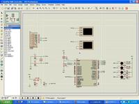
The circuit diagram for this simulation in Proteus VSM is :


4. I have done all this simulation using Text mode.I would comment further in my
next post

regards
m.yasir
 
Last edited by a moderator:

bluetooth gsm modem

thanks eng. yasir but i want to remember you about that i have to use the 8051 family and also i cant find any other phone work wz serial port but Ericsson T28
 

projects on gsm modem

yahya_shokr said:
thanks eng. yasir but i want to remember you about that i have to use the 8051 family and also i cant find any other phone work wz serial port but Ericsson T28

well your system development has nothing to with the type of microcontroller you choose.You can do it with any micrcontroller PIC,8051 or AVR etc.

The core issue is to understand the protocol for making the microcontroller communicate with mobile phone like m-bus,f-bus,rs232 ect.
I do not have much idea about T28.I would explore its hardware and interfacing protocol.
you also explore C168i.

regards
m.yasir
 

Status
Not open for further replies.

Similar threads

Part and Inventory Search

Welcome to EDABoard.com

Sponsor

Back
Top