nigh
Newbie level 6
Hi guys,
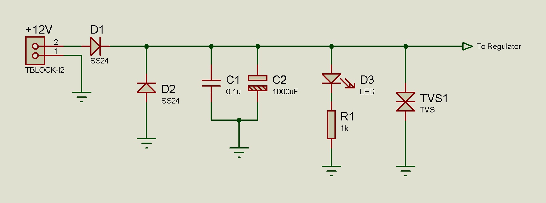
I have a circuit I am trying to understand. In the power input section, it has two protection diodes D1 and D2 (see attached diagram).
Now what i understand is : D1 is for reverse polarity protection. I am not sure what D2 is doing in the circuit. Diodes in this config (D2) are used to protect circuit from negative voltages but i am confused.
Please explain it to me guys.
thanks