Continue to Site

Welcome to EDAboard.com

Welcome to our site! EDAboard.com is an international Electronics Discussion Forum focused on EDA software, circuits, schematics, books, theory, papers, asic, pld, 8051, DSP, Network, RF, Analog Design, PCB, Service Manuals... and a whole lot more! To participate you need to register. Registration is free. Click here to register now.

[SOLVED] need the circuit explanation.

Status
Not open for further replies.

rasiris

Newbie level 3
Joined
May 6, 2011
Messages
3
Helped
0
Reputation
0
Reaction score
0
Trophy points
1,281
Activity points
1,302
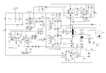
hi,i need circuit explanation of the following diagram perfectly, i have a explanation report but its not clear.
its an inverter
can any one help me out and explain it clearly?
i am posting both the circuit diagram and its explanatory report.
its urgent..:-x:-x:-x
 

Attachments

  • Description of function.pdf
    87.9 KB · Views: 83
  • inverter.GIF
    inverter.GIF
    44.3 KB · Views: 128

Could you be more specific? There's a ton of stuff going on, most of which doesn't seem too complicated, but explaining everything would take forever, and would probably end up being the same as your document. What parts of the circuit are you having trouble with?
 

The description document that you provide explains pretty much everything with detail. If you want an overview of what is happening, I can tell you.

Is a flyback inverter controlled by PWM, it has dead time control and non-overlapping provided by IC5/6/8. The IC1 is implementing an square wave oscillator which pulse width is controlled by the negative feedback loop and the controller implemented by IC12/13 that sense the output current and output voltage and generate an error signal and compare that against a reference. T5-8 are the predrivers or level shifters. T13/20/21/28 are the main power drivers.

That is the main loop, everything around it is support circuitry like the charge pump (IC10) used to regulate some internal VDDs. It has some overload protection implemented by IC9 and IC7.

The description document details more on the design choices for the values so give it another try to fully understand what is happening.
 
Status
Not open for further replies.

Similar threads

Part and Inventory Search

Welcome to EDABoard.com

Sponsor

Back
Top