Continue to Site

Welcome to EDAboard.com

Welcome to our site! EDAboard.com is an international Electronics Discussion Forum focused on EDA software, circuits, schematics, books, theory, papers, asic, pld, 8051, DSP, Network, RF, Analog Design, PCB, Service Manuals... and a whole lot more! To participate you need to register. Registration is free. Click here to register now.

Need some suggestion in LDO frequency compensation

Status
Not open for further replies.

wandola

Junior Member level 3
Joined
Jul 20, 2005
Messages
31
Helped
0
Reputation
0
Reaction score
0
Trophy points
1,286
Activity points
1,554
Hey guys,

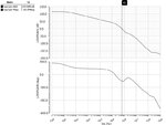
I have a three-stage LDO.

The simulation result is in attached (without compensation).

Looks like the dominant pole is only about 19 Hz, the second pole is around 90 kHz. UGB freq = 640 kHz.

The dominant pole is too low. And the DC gain is too high.

I tried to do a miller compensation. It turns out the dominant pole moves to very very low frequency (<1 Hz). And the compensation cap needs to be huge ~100 pF.

I am wondering is there other ways to do the compensation. I am not an expert in LDO/Opamp design. My specialization is in SAR ADC design.

thanks a lot guys.
 

Attachments

  • PMOSTr_cktsim_Idc5uA.jpg
    PMOSTr_cktsim_Idc5uA.jpg
    68.2 KB · Views: 174

Hi,

You seem to have a left half plane zero a little after the UGB any idea where that came from? Are you using an external capacitor and series resistance?
If you are using a series you can adjust it to place the zero where you want. This is an easy method if you external cap is quite huge. (>20nF)

Miller Capacitor is also called pole splitting compensation where it makes one pole more dominant and the other pole non dominant. This is why the dominant pole is at a lower frequency with miller compensation. Use the RC Miller compensation to add another LHP zero and see if it helps you.

Search "Annajirao Garimella", he has a bunch of papers on LDO compensation. The show some different strategies to compensate multiple stages.

I am also working on three stage LDO.
 

I am designing the LDO for a SoC application. therefore, the otuput cap is about 5 nF. No external cap, no ESR ...

I have no idea how the LHP zero comes into place...

Right now the problem is that, the 3rd pole and 4th pole are at low frequency and they are also very close to the UGB and the 2nd pole. I derived the position of the poles. But the 3rd and 4th poles are not where they are supposed to be.

I tried to tune the error amplifier. The 3rd and 4th poles donot move.......
 

It looks like your 3rd and fourth poles are complex poles.
Complex poles are likely with Compensation networks because you have a loop within a loop. The inner loop is the Compensation feedback and the outer loop is the LDO output voltage feedback. The inner loop may have complex poles.
But you say that the diagram you have posted is the one without Compensation. So I have no idea how it comes.
Your LHP Zero is also unexplained.

Can you show the circuit diagram?
 

120dB of dc gain for LDO!!. Just drop the gain to 60dB and you will have a very good design.
Not much could be told from the frequency plot. Would be good to look at the schematic.
 

Status
Not open for further replies.

Part and Inventory Search

Welcome to EDABoard.com

Sponsor

Back
Top