maark6000
Member level 5
Hello all, need to ask a question of the JFET wizards out there...
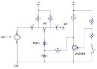
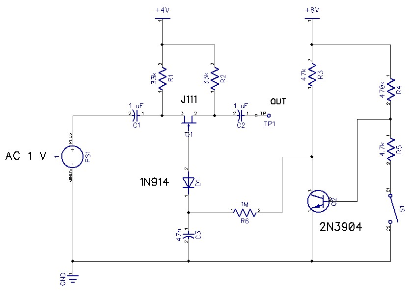
I'm trying to wrap my head around JFET bypassing, in other words using a JFET as an analog switch to either let a signal pass unimpeded or clamp it down so that no AC signal flows. In the attached schematic I've cobbled together the basic theme you see in many guitar pedal schematics. I've built this circuit, and I can't get it to work, and I'm stumped as to why. At the NPN's collector, when the switch is open I'm seeing a voltage of .75 V, and when the switch is closed it's up to 7.96 V. However, at the JFET's gate, the open voltage is .11 V, and not much better when closed at .33 V. I'm not getting the JFET to turn off. I've included the actual devices I'm using, like a J111 and a 1N914 etc... as far as I can tell they have similar characteristics of the devices used in all the various schematics I've seen. The J111 has a Vgs (off) of somewhere between -3 and -10 volts. Also, the AC signal here is audio... so maybe 1 Vpp. Thanks in advance for your help.
- - - Updated - - -
another thought occurs... I'm feeding the drain side of the JFET with a signal generator, a 1 Vpp sine wave, about 300 Hz, and I'm monitoring via my scope what's happening at the "out" pin... and i'm not seeing a reduction at all in the voltage of the sine wave. But, is that what I should expect when the JFET is "off?"
")
