Continue to Site

Welcome to EDAboard.com

Welcome to our site! EDAboard.com is an international Electronics Discussion Forum focused on EDA software, circuits, schematics, books, theory, papers, asic, pld, 8051, DSP, Network, RF, Analog Design, PCB, Service Manuals... and a whole lot more! To participate you need to register. Registration is free. Click here to register now.

Need some help with a project

Status
Not open for further replies.

ColdWave

Newbie level 3
Joined
May 15, 2011
Messages
3
Helped
0
Reputation
0
Reaction score
0
Trophy points
1,281
Activity points
1,307
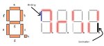
Hello, i'm new to the FPGA world as well on the forum. I kindly ask you guys to give me some assistance with a project. I've attached a picture to make the task easier to understand. I have to light up some of the LED segments on the board (those are like walls, can't go through them, just like a maze) and a special one, used for movement (this one has to blink while moving). The movement is done by the 4 pushbutton switches (assigned up, down, left, right) and I have to arrive at the last segment on the right (bottom). Once there, all segments have to blink, and use the reset switch to start all over again.
Any help would be highly appreciated! Thank you.
 

Attachments

  • Example.jpg
    Example.jpg
    39.7 KB · Views: 81

Map out all the possible paths through the maze and make each step along the path a state in a state machine. The LED segments are then controlled to light up differently as you progress through each state. The push buttons control the state transitions.
 

I'm sorry, but i don't fully understand what you're saying. The problem is, as I said in the earlier post, I'm pretty new to this world and i don't know all terms. How i thought about the problem:
1. Light up the segments according to the picture
2. Make one segment blink
3. Assign the buttons for movement
4. Block somehow the lit leds (make them walls), and pass only through the free path
5. Once finished, light all leds up
The hard part is how to do that, some directions or advices are welcomed.
 

I'm new too. I don't know how new you are so not sure whether this helps:
If you have problem with lighting up the LED: an output controls a LED segment, logic 1 is light and 0 is black. don't worry how the wire are connected when you program, just make a name for the output port. After the programming, on the real hardware you should get a map for the connections between pins and LEDs, buttons. Assign those pins and the program will do the rest.
Check the "State Machine" part in your VHDL text book.
Every LED is an output and every button an input. The blinking LED is the current state, it will transfer as the button is pushed. Like when 1-f is blinking, if UP is pushed, the state goes to 1-a is blinking, and if Down is pushed, state goes to 1-3, when Right, goes to 1-g. Assemble all states with how it will get to next state together, and the job is almost done.
and about the Blinking: you can relate the output port of LEDs to a clock in the programming, and the pulsing will make the blink.
Anyway, should study VHDL carefully in advance.
 

Here's a simple example to illustrate my points. Assume: 0 - 1 - 2 is the maze. For simplicity, there is only one path from 0 to 1 to 2. Each of these numbers is one of your segments. Now create a state machine having three states corresponding to these segments. State 0, State 1, and State 2. The only possible movements are from 0 to 1 with a right transition (button press). Then from State 1 you can transition either left to State 0 (with a left button press) or right to State 2 (with a right button press). In State 2 you can transition only left to State 1 (left button press).

The active state causes the corresponding segment to flash (AND each state with a 1Hz clock to cause a flashing segment when that state is active). As fredrichodie points out, all your buttons are inputs and each state represents one of the LED segments (paths).

You will probably also need to debounce the push button inputs. This can be done in hardware with a capacitor and pull-up resistor or in the fpga by latching the button with a fairly slow clock.

Mike
 

it is not a tough task in logic design world.
For ur example,u can use a FSM(Finite State Machine) to implement the design.
And FSM is just one way to complete ur task.

For a starter in logic design,FSM may be the better solution.

But firstly,you should know what is a FSM?and how to write a FSM?

If u understand what i said,maybe,you could clear with what to do next?

Just for referrence!
 

Thanks guys, at least now it makes more sense to me in theory! I'm gonna do a research on the finite state machine and I'll come up with questions on the encountered problems.
 

Status
Not open for further replies.

Part and Inventory Search

Welcome to EDABoard.com

Sponsor

Back
Top