Continue to Site

Welcome to EDAboard.com

Welcome to our site! EDAboard.com is an international Electronics Discussion Forum focused on EDA software, circuits, schematics, books, theory, papers, asic, pld, 8051, DSP, Network, RF, Analog Design, PCB, Service Manuals... and a whole lot more! To participate you need to register. Registration is free. Click here to register now.

Need sine to square wave convertor for 160 MHz !!!

Status
Not open for further replies.

Srilatha Padmanabhan

Newbie level 3
Joined
Feb 5, 2013
Messages
3
Helped
0
Reputation
0
Reaction score
0
Trophy points
1,281
Activity points
1,301
Hi all...
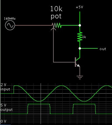
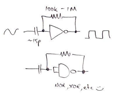
I need to convert a sine wave to square wave , but the difficulty I face is the frequency. the frequency of the input sine wave is 160 MHz.
Can anyone pls help me with this?!?!?!
 

There are microwave transistors that should be fast enough to do the job.

8857979200_1360083981.png


Adjust the pot until you obtain 50 percent duty cycle. (Be careful not to dial the pot to either extreme.)

A single transistor inverts the signal. You'll need a second stage if you want to match polarity.
 

hello brad,

Regarding the circuit in above fig, i feel it will have lot of power dissipation. If we use cmos invertor we possible would not get 50 % duty cycle (ON period will be less). Any work around for that ? you views
 

And just what do you think you'll achieve, for edge rate?
I can tell you that you're looking for better than 800MHz
bandwidth on every piece of the system from source to
destination. You will need sub-nS risetimes to look like a
square wave. What's your Cload and your Ipeak, to get
you that dV/dt?

Then bet on spending about 10% or more of your time
at Ipeak, and forget about being efficient. No free lunch
for you. Unless you can drive Cload to zero, including
Cself.

Now, an autobiased inverter at 130nm or below (bulk)
ought to be able to square it up "enough". You're also
probably looking at a 2:1 max taper in the clock tree
to not lose it downstream.
 

You might consider one of these high speed comparators.

But as noted, maintaining a square-wave at those frequencies requires very careful layout with a ground-plane and good decoupling of the circuits, possibly with microstrip transmission lines on the PCB to carry the high speed signals.
 

Hiya Srilatha,

A really simple circuit that has served me well is this:

7285683300_1360105017.jpg

It works by biassing the logic gate near it's transition threshold and using the input signal to nudge it either side, causing the output to snap high and low. If you used a 74AC00 or 74AC14, you could expect ~2ns rise/fall times. For the fastest operation, power the device at it's highest specified voltage, such as 5 - 6 volts.

Although the 74ACxx logic family is only specified for a ~125MHz max toggle frequency, I've successfully used it at 140 MHz and I suspect you could probably stretch it to 160... There are faster families (such as ECL) that you could use to the GHz and beyond, but their interface voltages are (usually) less convenient.

Oooh - I forgot to add:
There are other configurations of this circuit (such as including RC networks in the feedback wrapped around the gate) that offer improved low frequency performance and/or sensitivity. I've found the simple configuration shown to be adequate for most applications - just experiment with the coupling capacitor value if you want to go to lower frequencies. One caveat though: In the absence of an input signal, the gate's current consumption/power dissapation can rise as it loiters in its linear region. This isn't a problem if your signal is always present, and you can fix it (at the expense of some sensitivity) by applying a small voltage bias to the input if it troubles you...

Cheers :)
 
Last edited:
Status
Not open for further replies.

Similar threads

Part and Inventory Search

Welcome to EDABoard.com

Sponsor

Back
Top