Continue to Site

Welcome to EDAboard.com

Welcome to our site! EDAboard.com is an international Electronics Discussion Forum focused on EDA software, circuits, schematics, books, theory, papers, asic, pld, 8051, DSP, Network, RF, Analog Design, PCB, Service Manuals... and a whole lot more! To participate you need to register. Registration is free. Click here to register now.

[SOLVED] need opinions on my assembled 5v regulated power supply

Status
Not open for further replies.

T2eL

Newbie level 3
Joined
Apr 16, 2011
Messages
3
Helped
0
Reputation
0
Reaction score
0
Trophy points
1,281
Activity points
1,309
Greetings Everyone,

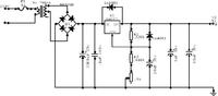
I've just completed assembling on a breadboard my first 5v regulated power supply using an LM317 and I would like your opinions if its not too much trouble. It works however the voltage is fluctuating between 4.99v to 5.01v. Is this normal and to be expected? I thought it would be more stable. I've included a schematic of what I've done. I tried to get the parts with values as close to the ones on the parts list but Ive had to settle for what was available. Hope you can help so I can move forward and use this to fiddle around with pic programming.


It's difficult to see but if there is a decimal point before the resistor values it should be OK, otherwise they are too high.
It is quite normal for there to be +1/-1 variation in the least significant digit if you are using a DVM so there may not be a problem.

If the transformer is center tapped, you might consider rewiring it so the center is ground and the two diodes on the right side of the bridge go to the ends of the winding. This will give you a little more voltage before the regulator and increase the stability of the transformer voltage slightly as well.

Brian.
 
  • Like
Reactions: T2eL

    T2eL

    Points: 2
    Helpful Answer Positive Rating
1.

Are you drawing from the center tap of an 18-0-18 V transformer? To get 9VAC? That will work.

Or are you tapping the center of a 9-0-9? In that case you may get 5 V output with no load. But once you attach a load it will drop below 5 V. THis is because there's two diode drops. Plus the regulator input needs to be 2 higher V than the output.

2.

The fuse can be a lower value.

If normal operation is 9V x .75A, then you're drawing 6.75W.

Your fuse will carry 6.75/220, or .03A.

You can use a 1/10 A fuse slo-blo if you can find one that low.

If you must use a fast blow then maybe 1/2 A is okay. Watch for surge current at power-up because the 3000 uF capacitor is like a dead short for a few cycles.

3.

Output from 4.99 to 5.01 is excellent.
 
  • Like
Reactions: T2eL

    T2eL

    Points: 2
    Helpful Answer Positive Rating
@betwixt
@BradtheRad

Thank you for your replies.

I may have not drawn the transformer a clearly as I had hoped. It is actually a multitap transformer with 0v,3v,4.5v,9v and 12v at 750mA. I have another variable power supply schematic that would use them but I decided not to make things too complicated for now and tapped into the 9v only. Would switching over to the 12v improve things? As it is the LM317 it is just warm, I suppose at 12v I would need an appropriately sized heatsink?

I wil keep an eye out for the lower rated - slow blow fuse.

@BradtheRad
''Watch for surge current at power-up because the 3000 uF capacitor is like a dead short for a few cycles."

Should I put some sort of diode or fuse protection in between the transformer and the 3300uF capacitor or is that overkill?

I have now added a red led+1k resistor right after the 3300uF capacitor as a power on indicator. I noticed that it takes a few seconds for it to fade out as it drains power from the large capacitor. Is there a faster way to drain the capacitors? I'm thinking a resistor in parallel to it.

Again, thank you for sharing. I appreciate it.
 

The 9V tap on the transformer is probably OK, if you find the output voltage drops under maximum load it may be because the voltage before the regulator has fallen too low for it to sustain 5V out. If that happens, your only option is to change to the 12V tap but it will increase the heat generated by the LM317 so a heat sink might be necessary.

Under NO circumstances connect a fuse in line with the capacitor alone, if the fuse blows it leaves the capacitor disconnected and in turn feeds unfiltered DC at the input of the LM317 - it wont like it!!
You can wire a fuse in series with the transformer secondary if you like but I would consider it overkill when the transformer only has 750mA rating. In reality what happens when you switch on is there is a rush of current to charge the capacitor but this in turn pulls the transformer voltage down for a moment (a fraction of a second) so it tends to 'self protect' itself.

The fading LED is just the residual charge on the 3300uF capacitor. It will do no harm and if you have a load on the output it will go out even quicker. If you add a bleed resistor it will simply waste power.

Brian.
 
  • Like
Reactions: T2eL

    T2eL

    Points: 2
    Helpful Answer Positive Rating
@betwixt

Thanks, I think I'm ready to move this on to a pcb now.
 

Status
Not open for further replies.

Part and Inventory Search

Welcome to EDABoard.com

Sponsor

Back
Top