neazoi
Advanced Member level 6
Hello I have found this **broken link removed**
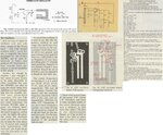
I have also managed to find an altered version of it from an old magazine which I attach.
Does anyone have more info on the original circuit? Where it has been published, or any construction details?
Also what if someone wants to video modulate it, where should the video signal be fed?
I have also managed to find an altered version of it from an old magazine which I attach.
Does anyone have more info on the original circuit? Where it has been published, or any construction details?
Also what if someone wants to video modulate it, where should the video signal be fed?