Continue to Site

Welcome to EDAboard.com

Welcome to our site! EDAboard.com is an international Electronics Discussion Forum focused on EDA software, circuits, schematics, books, theory, papers, asic, pld, 8051, DSP, Network, RF, Analog Design, PCB, Service Manuals... and a whole lot more! To participate you need to register. Registration is free. Click here to register now.

Need micro to produce anti phase pulse train with dead time.

cupoftea

Advanced Member level 5
Joined
Jun 13, 2021
Messages
2,611
Helped
54
Reputation
108
Reaction score
115
Trophy points
63
Activity points
13,685
Hi,
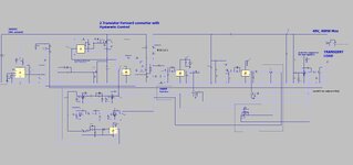
We have the following circuit in hardware....it receives the "gate" signal (shown in red), and then produces the other two pulse trains which are an anti-phase pulse train, sync'd by "gate"....but delayed from "gate" by about 300ns or so. (as can be seen). Please note the "dead" time in the waveforms

The "gate" signal is 100kHz. It has a duty cycle which varies between 0% and 50%.

Is there a particular cheap micro which is good for doing this?, ie, receiving "gate" , and then outputting the other 2 pulse trains?

What minimum frequency would the micro need to be at?
(schem, waveforms, and the LTspice sim of the hardware is as attached, please may you find it)

Delays with micro.jpg


Delays with micro_waveforms.jpg
 

Attachments

  • Delays with micro.zip
    1.5 KB · Views: 67
Many cheap micros can do this but you need to expand on your requirement:

1. Is it the leading or falling edge of 'gate' that syncs the cycle,
2. what happens at 0% duty cycle when the triggering signal is absent,
3. are the output pulses always constant length or do they also follow the duty cycle.
4. how much latitude is permissible in the dead time?

Perhaps showing a trace at say 10% duty cycle would help. Remember we don't all use your simulator.

Brian.
 
Hi,

PWM ... often comes from a control loop. Analog or digital. Then the overall performance depends on
* delay time (changed duty_cycle_in to changed duty_cycle_out)
* duty cycle resolution
* and maybe some other parameters like loop stability, syncing and jitter.

Thus - without knowing application details - I guess it's difficult to recommend something.

Just as wild guess: digital solution via PLD.

Klaus
 
Thanks
Its the leading edge that syncs it
At 0% duty it can just go "high all the time".
Output pulses follow the duty cycle
Dead time can be say anywhere 300ns to 500ns...as long as its pretty fixed at whatever it is.

Regarding the application, its for a SMPS synchronous rectifier drive, as attached. (LTspice and jpeg)

digital solution via PLD
Thanks, though i didnt think PLD was too good at delays.(?)
 

Attachments

  • Two tran forward_ONOFFcontrol_SYNCRECT_latch_COMP3.zip
    6.4 KB · Views: 65
  • 2 transistor forward with synchronous rectifiers.jpg
    2 transistor forward with synchronous rectifiers.jpg
    202.5 KB · Views: 68
Last edited:
Quite easy to do, inclkudingh controlled burst length :

1687089444551.png


Whats on this SOC :

1687089504287.png


Drag and drop these functions onto design canvas, config, route. One chip. Could create multiple
channels if needed.

IDE and compiler free, board for this ~ $15, more if a lot of I/O is needed.


Regards, Dana.
 
Thanks, may i ask, do you mean the "PSoC creator" dev board is $15?...or the chip to do the job, which you specifiy with the PSoC creator would be $15?

...as you know, $15 is alot....would prefer a cheap micro solution to this
 
Now thats just a board to do the dev. I showed the example as a
PSOC 5LP, but a 4M family should do the job.


A CY8C4245 part should do the job. Sub $2 in single piece pricing. Note is resources are reduced
from my prior post pic, but more than capable of doing your request.

The 4M board is more like $ 25 if I am not mistaken, check me on this.


Regards, Dana.
 
Last edited:
Thanks, and i reckon though, that a micro running at 20MHz would be good for the job of the top post.?...but it would need one or two external logic gates for help....
20MHz, would (please tell, am i right?) allow the micro to receive an "edge", at one of its digital inputs, and then put out a logic output change (on a different I/O pin) 100ns after receiving that edge?

There are other times, when the micro has to receive a falling edge, then take a signal low within some 20ns of that edge...and thats too much to expect from a micro....so the micro would have to use the help of an external NAND gate for that.
 
Hi,
20MHz, would (please tell, am i right?) allow the micro to receive an "edge"
how can we know?
We don´t even know what micro you prefer and how many clock cycles it needs to process a single instruction.

If your gate signal comes with 100kHz, then from one rising edge to the nect rising edge it´s just 10us.
.. and the falling edge?

And then you talk about a delay of 300ns. That´s just 6 clock cycles ...

I guess you need to elaborate what you expect from the micro with timing diagrams, flow chart ...

Klaus
 
basically, the micro needs to receive a digital input on one pin, then output a digital output on another pin, within 100ns of the digital input having been received.

With a 4MHz PIC, it could receive a digi input on one pin, but it would be 1us later for it to be able to give the corresponding output.......so actually, i guess for this 100ns "response time", we would need a 40MHz PIC......thats getting very high speed for a PIC.
 
Hi,

if I understand correctly .. you want
* read input
* delay
* write output
* jump loop

Now let´s say the whole loop takes 20 clock cycles, then the jitter will also be 20 clock cycles peak to peak.

Additionally this simple task takes 100% of processing power. No chance to do something else. No key press, no LED, no communication. nothing. Just run the loop with maybe 4 instructions.

Thats why - in my opinion - a micro is not the best choice.

Again: we need more information...

Klaus
 
Thanks, and i reckon though, that a micro running at 20MHz would be good for the job of the top post.?...but it would need one or two external logic gates for help....
20MHz, would (please tell, am i right?) allow the micro to receive an "edge", at one of its digital inputs, and then put out a logic output change (on a different I/O pin) 100ns after receiving that edge?

There are other times, when the micro has to receive a falling edge, then take a signal low within some 20ns of that edge...and thats too much to expect from a micro....so the micro would have to use the help of an external NAND gate for that.

First case :

1) You want retirggerable ?
2) What is pulse width needed for output pulse ?
3) Would a 48 Mhz root clock suffice, 20.8 nS ? So 5 x that for delay versus 100 ns even delay you asked for ? Something like this :

1687280891711.png


Second case :

1) A falling edge generates a latched output or is simple 20.8 nS delay

Both solutions, no external gates, all HW approach. No onboard processor involvement in this, its 100% available for the other tasks. The PSOC can do this.


Regards, Dana.
 
Last edited:
Here is the delay 100 nS, note somce my res is fed by 48 Mhz
I wind up being either a litle slower or a little faster that 100 nS.

All onchip.


1687361675009.png


Regards, Dana.
 
That part is the older non ARM series of parts with declining usage. It works wilh
PSOC Designer, not Creator, totally different IDE and support for that dramatically
declined.

Its incapable of doing, as near as I can tell, the timing you were looking for.

If you are looking for a different design I would post at Infineon site to see what long term
support looks like.

The families for new work are PSOC 4, 5LP, 6.

The family my proto test for your timing was PSOC 4M.


Regards, Dana.
 
By the way, if you are not going to use the other 95% of the PSOC, the other
analog and digital and fabric, there must be programmable logic out there that
would do the job. Just a thought.

Another thought, the 4M family is lower cost than the 5LP, but the 5LP board
can be had for ~ $15, and it has 2 5LPs on it, one dedicated to programming
and the other to target. And you snap off prog side when you are done. You
can use the prog side stand alone, but it has very little I/O pinned out. Or
continue to use as a prog board.

Or use the 4M board, more like a $ 25- $ 30 board.


Regards, Dana.
 

LaTeX Commands Quick-Menu:

Similar threads

Part and Inventory Search

Welcome to EDABoard.com

Sponsor

Back
Top