happyree
Newbie level 4
Hello everyone!
when I do post-simulation with assura extracted-view after the lvs and rcx step, I find an odd problem.
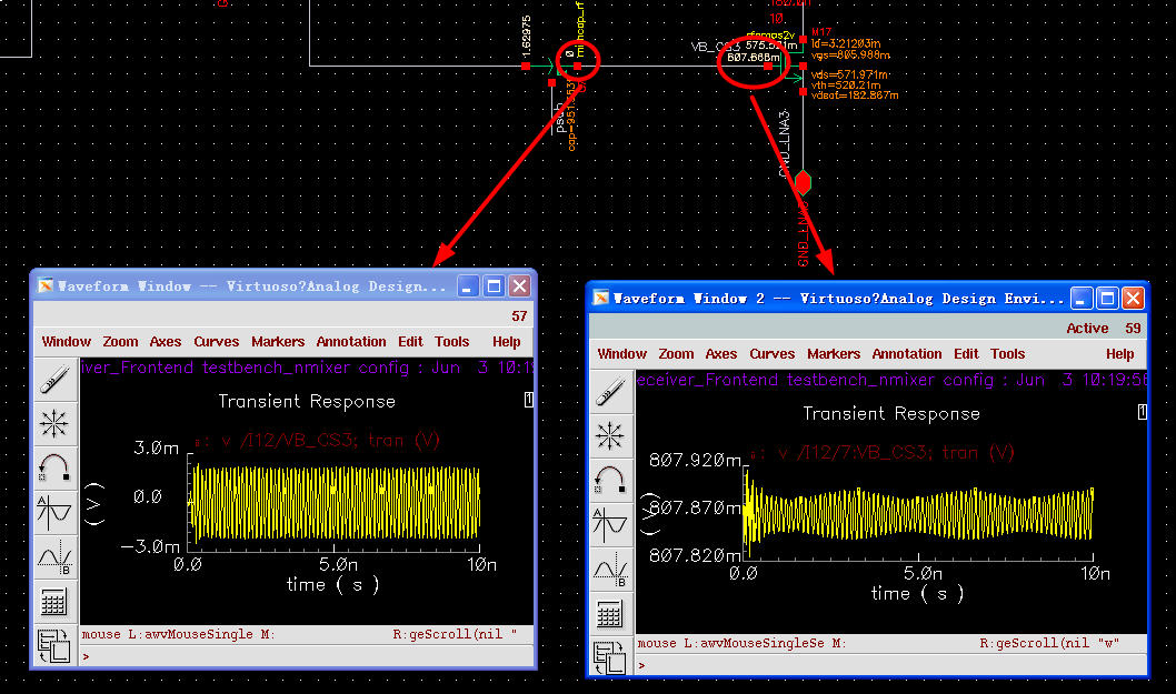
As is showed in the picture a rf_mim cap is directly connected to the gate of a MOS transistor. But their DC voltage are different. And it seems the rf signal of the two points have no relationship. Besides, I found that DC voltage of all the "plus" of other rf caps are 0 V.
before, the post-simulation results were right. Then I did some changes and copys of the shematic and layout, this problem comes up. If I delete part of the circuit and layout , it disappears. but then I have to redraw the layout, it's too much work.
so I hope someone can help about this.
Thanks a lot!
when I do post-simulation with assura extracted-view after the lvs and rcx step, I find an odd problem.
As is showed in the picture a rf_mim cap is directly connected to the gate of a MOS transistor. But their DC voltage are different. And it seems the rf signal of the two points have no relationship. Besides, I found that DC voltage of all the "plus" of other rf caps are 0 V.
before, the post-simulation results were right. Then I did some changes and copys of the shematic and layout, this problem comes up. If I delete part of the circuit and layout , it disappears. but then I have to redraw the layout, it's too much work.
so I hope someone can help about this.
Thanks a lot!