Continue to Site

Welcome to EDAboard.com

Welcome to our site! EDAboard.com is an international Electronics Discussion Forum focused on EDA software, circuits, schematics, books, theory, papers, asic, pld, 8051, DSP, Network, RF, Analog Design, PCB, Service Manuals... and a whole lot more! To participate you need to register. Registration is free. Click here to register now.

Need help with fixing the wacom ctl-471 connector

Status
Not open for further replies.

Bagile

Newbie
Joined
Oct 16, 2020
Messages
4
Helped
0
Reputation
0
Reaction score
0
Trophy points
1
Activity points
25
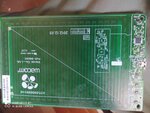
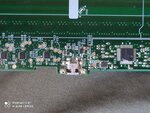
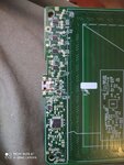
I have a wacom tablet on which the connector lost contact with the pcb. I'd like to solder the cable directly to the pcb but i cant find where the connections are on the pcb. I put up couple of pictures of the pcb, if you cant see something clearly ill do it again. Thanks in advance!
 

Attachments

  • IMG_20201016_142829.jpg
    IMG_20201016_142829.jpg
    5.2 MB · Views: 225
  • IMG_20201016_142855.jpg
    IMG_20201016_142855.jpg
    3.7 MB · Views: 236
  • IMG_20201016_142806.jpg
    IMG_20201016_142806.jpg
    1.8 MB · Views: 235

Hi,

on the pictures it is hard to tell where the USB pins are going to. I assume the 64 pin IC in a TQFP package is a microcontroller. By doing a web-seach I came up with the following datasheet [1]. Unfortunately it is in japanese. Nevertheless, have a look at the pin out on page 5 and identify your USB related pins. Than use a multimeter (Ohm/Resistance - Mode) to follow the track leaving this pins toward the connector. There might be a series resistor or some kind of protection IC between the MCU and the connector.

[1] https://www.onsemi.com/pub/Collateral/LC87F9W48AJP-D.PDF

BR
Thanks for the reply! Im new to this so i will need just a little more help. So i know the 3 pins are D+, D- and Vbus but im not sure about the other two. I think they might be DPUP and UFILT but i really am not sure.
 

If the connector has 5 pins, the two remaining ones are GND and ID.

It looks like UFILT has a filtering purpose, see Fig. 4. I assume DPUP has a power direction control purpose.
 

If the connector has 5 pins, the two remaining ones are GND and ID.

It looks like UFILT has a filtering purpose, see Fig. 4. I assume DPUP has a power direction control purpose.
Im guessing Vdd is for ground and Vss is for ID right? And if so do i follow Vdd1 and Vss1 or others
 

Hi,

if you want to connect the individual wires of your USB cable directly to the PCB you have to

(i) identify the individuel wires. There is a color coding [1] & [2]. The ID/Sense pin might already be connected to GND on the PCB. So a 4 wire cable might be sufficient (see [2]).
(ii) find the next low resistive solder joint on the PCB starting from the connector pin towards the corresponding MCU pin.
(iii) solder the corresponding wire to this solder joint.
(iv) create some strain relief for your cable.

[1] https://hello-gsmplus.blogspot.com/2015/10/usb-cable-pinout.html
[2] https://en.wikipedia.org/wiki/USB_hardware
BR
--- Updated ---

Hi,

Im guessing Vdd is for ground and Vss is for ID right?

Vdd or Vcc usually denots the positive supply voltage. Vss or Vee usually denotes the negative voltage or in a singele supply rail system, the system ground GND.

BR
 
Last edited:

Hi,

if you want to connect the individual wires of your USB cable directly to the PCB you have to

(i) identify the individuel wires. There is a color coding [1] & [2]. The ID/Sense pin might already be connected to GND on the PCB. So a 4 wire cable might be sufficient (see [2]).
(ii) find the next low resistive solder joint on the PCB starting from the connector pin towards the corresponding MCU pin.
(iii) solder the corresponding wire to this solder joint.
(iv) create some strain relief for your cable.

[1] https://hello-gsmplus.blogspot.com/2015/10/usb-cable-pinout.html
[2] https://en.wikipedia.org/wiki/USB_hardware
BR
--- Updated ---

Hi,


Vdd or Vcc usually denots the positive supply voltage. Vss or Vee usually denotes the negative voltage or in a singele supply rail system, the system ground GND.

BR
Okay so one last question, if i have multiple Vss's and an AVss should i connect them all as ground or what?
 

Hi,

you have not to care about the individual connections of the microcontroller. The correct connection has already been realized on the PCB.

Use a multimiter in ohm-mode and look for the next solder joint/pad which is in the closest vicinity of the connector, as you want to connect your USB cable direct to the board. The multimiter should show a restistance close to zero if one probe tip is placed on the usb connector pad and the other one on the “near“ solder joint.

You could also depopulate the connector and solder the individual USB cable wires to the USB connector pads on the board. But as far as I understood you initial post, this pads/connection is damaged. If those pads are still fine connect the wires to those pads.

BR
 

Status
Not open for further replies.

Part and Inventory Search

Welcome to EDABoard.com

Sponsor

Back
Top