Continue to Site

Welcome to EDAboard.com

Welcome to our site! EDAboard.com is an international Electronics Discussion Forum focused on EDA software, circuits, schematics, books, theory, papers, asic, pld, 8051, DSP, Network, RF, Analog Design, PCB, Service Manuals... and a whole lot more! To participate you need to register. Registration is free. Click here to register now.

Need help with dipole antenna

Status
Not open for further replies.

ji3n

Newbie level 5
Joined
Jul 1, 2011
Messages
8
Helped
0
Reputation
0
Reaction score
0
Trophy points
1,281
Activity points
1,345
Hi, i am trying to design a koch fractal dipole antenna for a GPS with frequency of 1.5GHz, my supervisor says that my antenna needs a ground. But the thing is i thought dipole antenna doesnt need a ground? Any kind advice will help a lot.. thank you:wink:
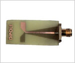
 

Hi, its a patch antenna on a FR4 board.. im kind new with antenna please bare with me :oops: thank you
 

HI
you can design antenna with two layers and one of layer have one branch of dipole.
" one branch on the bottom and one branch on the top of FR-4 " y can design antenna
having two patch on the top of FR-4. you can find dipole sample using FR4 board on
the internet. If you use CST, HFSS... u can find it on the macro in help page of software
 

hi
yes your antenna need ground but your supervisor did not give you any paper about this
 

Hi ji3n,

Aren't you telling about a monopole rather than a dipole? It DOES use a ground plane.
But later you mention a patch antenna. It does use a ground plane too, but this is very different to a Koch fractal dipole.
Can you clarify?
Regards

Z
 

Im very sorry to be confusing. I'll try to clarify as best as i can. :oops:

My project is about comparing a normal patch dipole with a patch koch curve dipole that operates in the GPS frequency of 1.5GHz.

It is to show with a fractal antenna i am able to shrink normal antenna size while being able to operate in the same frequency.

It is a patch antenna because i need to assume the antenna is in the GPS device.

So when i gave my supervisor to have a look on the dimensions of my patch dipole antenna, she asked "where is the ground plane?", i was shocked because i thought dipole antenna doesn't need a ground plane.

I really appreciate the replies from you guys, thank you :-D
 

Hi ji3n,

it is confusing. A "patch" and a "koch curve dipole" are different types of antennas.
Maybe you want a printed dipole instead o a "patch dipole"?
Regards

Z
 

hi ji3n
i think u did not ask your supervisor about your project carefully .i think she actually want dipole kind like LPDA or same this

LOG PERIODIC FRACTAL KOCH ANTENNA FOR UHF BAND APPLICATIONS
by : M. N. A. Karim, M. K. A. Rahim, H. A. Majid, O. Ayop
M. Abu and F. Zubir
Progress In Electromagnetics Research, PIER 100, 201{218, 2010
 

hi everyone,

zorro, maybe im the one that is confused. Patch dipole and printed dipole is it different? :oops:

ferdows, i think thats the one. But i only require to do a simple T shape. thanks you

sorry for the trouble everyone :oops:
 

HI
I understand what you have said. you can read "Microstrip antenna handbook design" it's very useful to design. if you want to design T shape, it's very simple to design. you can use antenna having image Dipole-Antenna-X-Band-Microstrip.jpg
 
Hi ji3n,

A "printed antenna" or "microstrip antenna" is an antenna using printed circuit (or equivalent) structure or construction. It can be a patch, a dipole, a slot, etc.
Dipole and patch are different types of antenna.
Regards

Z
 
  • Like
Reactions: ji3n

    ji3n

    Points: 2
    Helpful Answer Positive Rating
Dear zorro,
I think i understand now. So now i need to design a printed dipole and a printed koch curve dipole. And compare them.
 

In general terms, a patch antenna (on a PCB) operates by using two "radiating slots" formed at the ends of the patch antenna, between the top metal, and the ground plane below it. In the ideal case, the ground metal does not radiate, just supports the slots formed in the substrate.

Dipoles are also typically 1/2 wavelength structures ,but generally do not use a ground plane in close proximity to the radiating elements.

From looking at the paper ferdows mentioned (full PDF), check out page 7 for images of the fabricated dipoles. They are two-layer circuits, but do not have a true ground plane... yet they have conductors on layer 1 (top) and layer 2 (bottom) of the board. Maybe your supervisor meant you'd need metal on both sides of the PCB, but calling layer 2 a ground plane is incorrect. It's simply a second conductive metalized layer, and most-certainly would NOT be grounded.
 

Status
Not open for further replies.

Part and Inventory Search

Welcome to EDABoard.com

Sponsor

Back
Top