Continue to Site

Welcome to EDAboard.com

Welcome to our site! EDAboard.com is an international Electronics Discussion Forum focused on EDA software, circuits, schematics, books, theory, papers, asic, pld, 8051, DSP, Network, RF, Analog Design, PCB, Service Manuals... and a whole lot more! To participate you need to register. Registration is free. Click here to register now.

Need help to stablize transistor by resistive load in output

Status
Not open for further replies.

ashishchandra

Junior Member level 2
Joined
Jun 9, 2009
Messages
23
Helped
5
Reputation
10
Reaction score
4
Trophy points
1,283
Location
India
Activity points
1,460
Stability circles

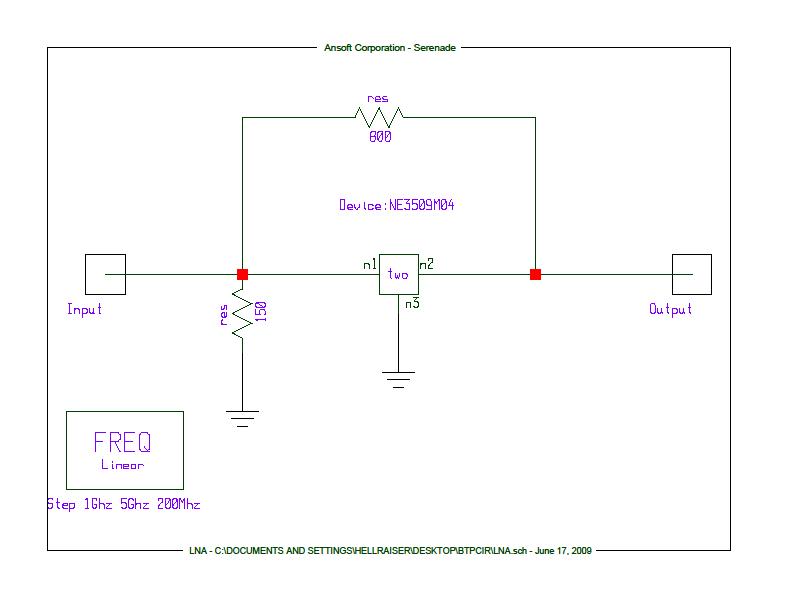
i m making an LNA with s-parameters values as follows at 2.4Ghz:
1)s11 = 0.775 ang(-68.1)
2)s12 = 0.079 ang(54.5)
3 s21 = 5.602 ang(117.4)
4)s22 = 0.437 ang(-42.3)

and i want to stablize the transistor by a resistive load in output.but i m not able to find suitable resistive load which can stabilize this transistor .please help me in this regard.....
 

Re: Stability circles

Try this...
 
Re: Stability circles

thanks for the help dude...but how did you get these values?
man if u have any refence or material please send it 2 me....my mail id is saiyan4aks@gmail.com
 

Re: Stability circles

Any linear RF circuit simulator (freeware or not) will do this job.
 

Re: Stability circles

actually my problem is how did you get the values of passive elements and the construction using simulator(whatever u r using)...
 

Stability circles

To stabilize it just put a low value resistor in shunt to the s2p file. How ever you will loose the gain, NF and RL etc.
So it is better to do the design using good simulator.
You need to plot the NF circles and gain circles.
Chose the impedance and then play with it.
 

Re: Stability circles

The circuit presented was tuned to lose minimum on NF and Gain. The circuit is placed at the output of the LNA, and luckily the initial instability was not so bad.

One thing that should remember is, if a circuit presents potential instability, doesn’t mean will oscillate. Depends by series of factors, as input/output impedances at particular frequencies.

There are hundreds of articles or RF books that present LNA impedance matching. Just read few of them.
 

Re: Stability circles

vfone said:
The circuit presented was tuned to lose minimum on NF and Gain. The circuit is placed at the output of the LNA, and luckily the initial instability was not so bad.

One thing that should remember is, if a circuit presents potential instability, doesn’t mean will oscillate. Depends by series of factors, as input/output impedances at particular frequencies.

There are hundreds of articles or RF books that present LNA impedance matching. Just read few of them.

heu vfone may have your chat id....i have many question about the LNA designing..it will be a great help for me to understand this area properly.....

Added after 1 hours 43 minutes:


Well this is the image for the circuit i made to stabilize the LNA.When i increase the value of feedback resistor the value of k increases.can i use this configuration to stabilize the circuit??
 

Re: Stability circles

In principle you can. Check if is possible to integrate the feedback resistor into the transistor bias.
 

Status
Not open for further replies.

Part and Inventory Search

Welcome to EDABoard.com

Sponsor

Back
Top