jeswanth123
Junior Member level 2

- Joined
- Mar 6, 2011
- Messages
- 20
- Helped
- 0
- Reputation
- 0
- Reaction score
- 0
- Trophy points
- 1,281
- Activity points
- 1,471
Hello all senior ENGINEERS,
THANKS TO ALL THOSE DEXTERS AND INTELS IN ADVANCE.
I am not an electronics students, I dont know much of the electronics. I get help from this forum, whenever I need.
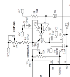
I want to calculate the voltage and or current from the op-amp max495 to the pin MD. Datasheet attached. Its very simple to calc, but I dont know how :-(
I have a laser driver circuit, which is finished and working properly for one laser diode which was shipped with the circuit. I tried replacing it with my laser diode. It works fine some times and fails some times.
The circuit is based on the MAX3766EEP, I have attached the circuit given in the official pdf.
The problem is that the LD I am using has a monitor diode which requires at-least 5 volts, I presume. Its NX5306EK form NEC. But the max3766 dont handle that voltage, I presume. And so some times when there is no enough current on the monitor pd, the FAIL on the max3766 is latched or starts and circuit wont work untill i restart. I tried reverse biasing the monitor diode which is the actual scenario used by all while connecting the PD but it failed and works when connected in BIAS.
So, I want to bypass that shutdown or fail by the max3766, as given in the max3766evkit. They connected the monitor diode pin directly to max495. So It drives some voltage and current to the MD pin, so there is no need to connect the monitor diode pin at all. Now the problem is solved. But As my circuit is already finished. I, Want to calc or know the voltage and or current from the max495 to that pin. So that I can add extra components lm358 or etc to drive that voltage to that md pin and solve the problem.
This is my solution, I hope you guys have more solutions.
Thanks again.

