Continue to Site

Welcome to EDAboard.com

Welcome to our site! EDAboard.com is an international Electronics Discussion Forum focused on EDA software, circuits, schematics, books, theory, papers, asic, pld, 8051, DSP, Network, RF, Analog Design, PCB, Service Manuals... and a whole lot more! To participate you need to register. Registration is free. Click here to register now.

need help regarding ir sensor module

Status
Not open for further replies.

hiten09

Member level 2
Joined
Dec 31, 2011
Messages
51
Helped
0
Reputation
0
Reaction score
0
Trophy points
1,286
Activity points
1,630
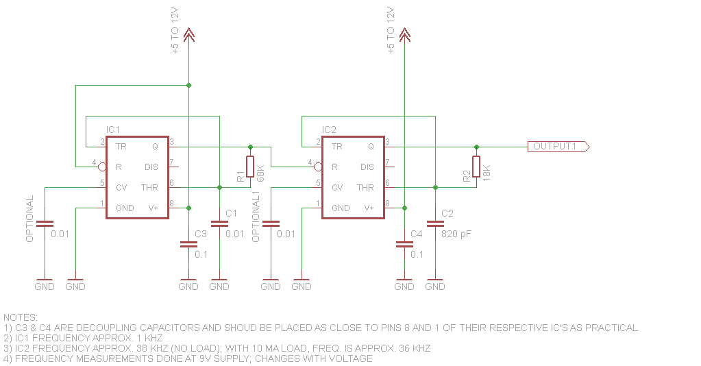
i wanted to build a ir sensor module of 38khz, for that i m making the transmitter part through 555 ic and in receiver section i m using ir receiver ie. TSOP1738. but i am confused with the circuit diagram of transmitter. 555 driving IR LED.PNG
i am confused whether the above circuit is correct or i found 2 3 more which are as follows..
**broken link removed**

i am confused which circuit is correct if anyone have the working circuit diagram please post it.
i also wnted to know the range of this ir module i mean how much far apart we can keep the transmitter and receiver
 

Attachments

  • 555 datasheet.pdf
    285.5 KB · Views: 227
Last edited by a moderator:

This type of transmitter is not suitable with TSOP 1738,
receiver do not work with continous carrier.
Transmitter must send short bursts of 38kHz carrier.

Suitable Data Format

The circuit of the TSOP17.. is designed in that way that
unexpected output pulses due to noise or disturbance
signals are avoided. A bandpassfilter, an integrator
stage and an automatic gain control are used to
suppress such disturbances.
The distinguishing mark between data signal and
disturbance signal are carrier frequency, burst length
and duty cycle.
The data signal should fullfill the following condition:
• Carrier frequency should be close to center
frequency of the bandpass (e.g. 38kHz).
• Burst length should be 10 cycles/burst or longer.
• After each burst which is between 10 cycles and 70
cycles a gap time of at least 14 cycles is neccessary.
• For each burst which is longer than 1.8ms a
corresponding gap time is necessary at some time in
the data stream. This gap time should have at least
same length as the burst.
• Up to 1400 short bursts per second can be received
continuously.

https://www.engineersgarage.com/sites/default/files/TSOP1738.pdf

https://www.edaboard.com/threads/232028/
 
Last edited:

ok man , so what should i do as i want to make a ir module which can transmit the beam upto 2 feet and receiver could accept it , do you have any schematic containg ir transmitter and receiver both which can solve my problem? or any link?
 

Here is one of many possible designs:


John
 

john,
this is transmitter? or receiver?
 

It's for the transmitter. The IRED(s) and resistor go on the output. One of the 555's makes a 38 KHz square wave. The other 555 turns the 38 KHZ 555 on and off at about 1 KHz to give the required pattern. You said you were using the TSOP1738 for receiver.

John
 

is it working? did you tried it yourself?
and john, in receiver section i have to use the tsop1738? the same circuitary as given in datasheet of tsop1738?
 

Status
Not open for further replies.

Part and Inventory Search

Welcome to EDABoard.com

Sponsor

Back
Top