ALERTLINKS
Advanced Member level 4
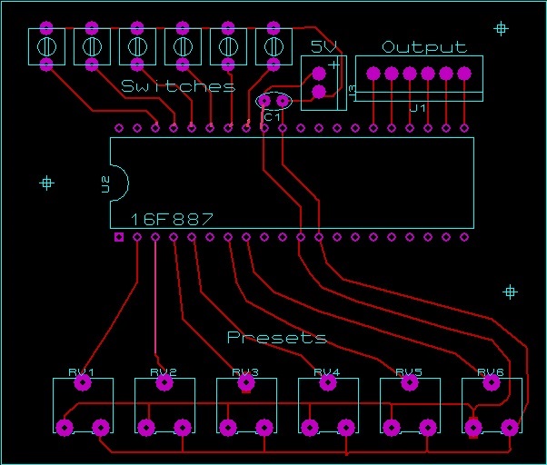
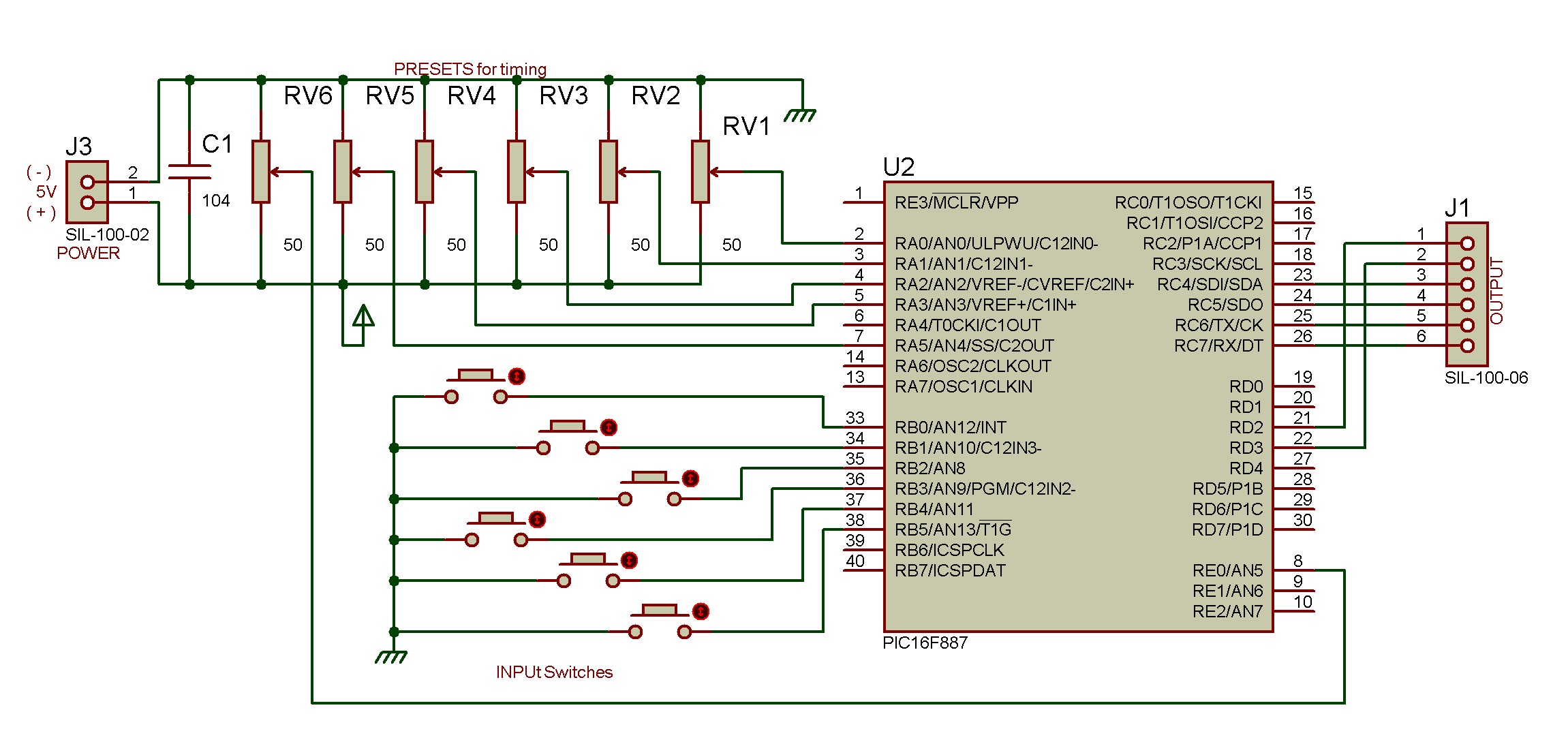
"Prts List"
Presets 10k-- 6.
Push switches-- 6.
Capacitor 104--1.
PIC16F887--1.
Connectors, PCB board,etc.
5V is common with relay board. Output connects with trig input. Timing is set by setting presets.
Hex file is attached
And videos of 16F887 in operation.