Continue to Site

Welcome to EDAboard.com

Welcome to our site! EDAboard.com is an international Electronics Discussion Forum focused on EDA software, circuits, schematics, books, theory, papers, asic, pld, 8051, DSP, Network, RF, Analog Design, PCB, Service Manuals... and a whole lot more! To participate you need to register. Registration is free. Click here to register now.

Need Help In using Counter 0 in PIC16F873A

Status
Not open for further replies.

Brejain

Newbie level 3
Joined
Jan 5, 2010
Messages
4
Helped
0
Reputation
0
Reaction score
0
Trophy points
1,281
Location
Coimbatore
Activity points
1,322
Hi ...
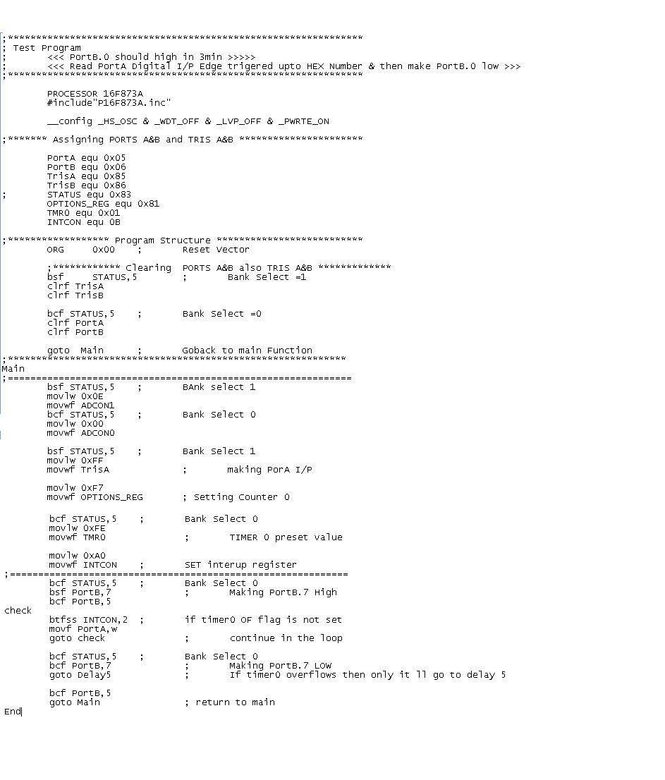
I am new to Pic . I have to implement a code which has to make Port B.0 pin high on after every 3min.But the Port B.0 should be turned off by checking the 10 edge triggering in the Port A.4 pin. So i tried to implement counter 0.Time delay of 3min is working fine for me. But the edge triggering I/P at Port A.4 is not affecting the counter.Its not causing an interrupt at INCON register.I am giving the code below with delay of 3min omitted.


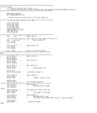
Delay subroutine is omitted as its working fine for me.
Thanking all who tries to help
 

Hi,

A few things:

1. No need to define PortA, PortB, TrisA, TrisB, OPTIONS_REG, TMR0, INTCON. Since you have included "P16F873A.INC", just use PORTA, PORTB, TRISA, TRISB, OPTION_REG, TMR0, INTCON and no need to decleare these SFRs. [Word of caution: You HAVE to write these SFRs in caps(upper case) otherwise you have to equate all of them].

2. Right after "ORG 0x00", you cleared the PORT and TRIS bits. No need. Just do:
Code:
   BSF        STATUS, RP0
   MOVLW   0xFF
   MOVWF   TRISA
   CLRF       TRISB
   BCF        STATUS, RP0
   CLRF      PORTB
right after "MAIN".

3. If you meant to disable ADC, you should've written:
Code:
   MOVLW   0x07
   MOVWF   ADCON1
No need to write anything to ADCON0 as the above 2 lines disables ADC. Also disable comparator by writing.
Code:
   MOVLW   0x07
   MOVWF   CMCON

4. Instead of 0xF7, write 0xF8 to OPTION_REG:
Code:
   MOVLW   0xF8
   MOVWF   OPTION_REG
Writing 0xF7 sets prescaler as 1:256. You don't need it, unless you actually intended to do that. Writing 0x78 assigns no prescaler to TMR0.

5. If you wanted 10 triggers, you should assign 246 and not 0xFE:
Code:
   MOVLW   .246
   MOVWF   TMR0

6. You got your checking all messed up. It should be like:
Code:
CHECK
   BTFSS   INTCON, T0IF
   GOTO    CHECK
   ....REST OF CODE
Here it checks for raising of TMR0 interrupt flag and continues out of the loop after the flag is raised. The way you wrote it, it's never going to come out of the loop.

I guess that's all. But if it still doesn't work, tell us about it.

P.S. It would be nice if you could post your codes within code tags in text format.
Tahmid.
 

Hi Tahmid,

First of all thanks alot for the sincere effort u r putting here..

Regarding our issue.. i would like to point out few things. I cleared TRISB to make it o/p
OK leave it i have made changes according to wht u told. I HAVE used pORT B.5 pin to make sure code is running when put in kit.So u dont worry abt tht.but the prob is the preset value of timer 0 is not getting affcted at all.. i am including the new code below..
#####################################################
PROCESSOR 16F873A
#include"P16F873A.inc"
__config _HS_OSC & _WDT_OFF & _LVP_OFF & _PWRTE_ON

;****************** Program Structure **************************
ORG 0x00 ; Reset Vector

banksel TRISA
CLRF TRISA
CLRF TRISB
goto Main ; Goback to main Function
;************************************************************
Main
;=============================================================
MOVLW 0x07
MOVWF ADCON1

banksel TRISA ; Bank Select 1
movlw 0xFF
movwf TRISA ; making PorA I/P

movlw 0xF8
movwf OPTION_REG ; Setting Counter 0

bcf STATUS,5 ; Bank Select 0
movlw 0xF6
movwf TMR0 ; TIMER 0 preset value

movlw 0xA0
movwf INTCON ; SET interup register
;============================================================
bcf STATUS,5 ; Bank Select 0
bsf PORTB,7 ; Making PortB.7 High

check
btfss INTCON, 2 ; if timer0 OF flag is not set
goto check ; continue in the loop

bcf STATUS,5 ; Bank Select 0
bcf PORTB,7 ; Making PortB.7 LOW
goto Delay5 ; If timer0 overflows then only it ll go to delay 5
bcf PORTB,5 ; test
goto Main ; return to main
goto Skip ; Skip Subroutine
Skip
end

######################################################

Also i would like to know wht is meant by prescalar in timer n counter
 

Hello,
I think I see where you're going wrong.
You wrote:
Code:
movlw 0xA0
movwf INTCON
It should be
Code:
clrf INTCON
This is because when you enable interrupt, the PIC tries to go to the interrupt vector 0x04. But in your program there is no ISR. (I've shown this below).

Added after 5 minutes:

And one more thing,
I get you clear TRIS for output. But there's no need to write that after org 0x00 as you are doing this later:
Code:
movlw 0xff
movwf TRISA
Just add this there:
Code:
movlw 0xff
movwf TRISA
clrf TRISB
ok, anyway, ADCON1 is in bank1. Change that.

Here's the change.
At the end of the program if you want to repeat write:
Code:
PROCESSOR 16F873A
#include"P16F873A.inc"
__config _HS_OSC & _WDT_OFF & _LVP_OFF & _PWRTE_ON

;****************** Program Structure **************************
ORG 0x00 ; Reset Vector

goto Main ; Goback to main Function
;************************************************************
Main
;=============================================================

banksel TRISA ; Bank Select 1
movlw 0x07
movwf ADCON1
movlw 0xFF
movwf TRISA ; making PorA I/P
clrf TRISB

movlw 0xF8
movwf OPTION_REG ; Setting Counter 0

bcf STATUS,5 ; Bank Select 0
clrf PORTB
movlw 0xF6
movwf TMR0 ; TIMER 0 preset value

movlw 0x00
movwf INTCON ; SET interup register
;============================================================
RESTART
bsf PORTB,7 ; Making PortB.7 High
bsf PORTB,5

check
btfss INTCON, 2 ; if timer0 OF flag is not set
goto check ; continue in the loop

bcf PORTB,7 ; Making PortB.7 LOW
goto Delay5 ; If timer0 overflows then only it ll go to delay 5
bcf PORTB,5 ; test
bcf INTCON, TMR0IF ;we forgot to clear the flag
;goto Main ; don't do this
goto RESTART
end
And if you dont want to repeat:
Code:
PROCESSOR 16F873A
#include"P16F873A.inc"
__config _HS_OSC & _WDT_OFF & _LVP_OFF & _PWRTE_ON

;****************** Program Structure **************************
ORG 0x00 ; Reset Vector

goto Main ; Goback to main Function
;************************************************************
Main
;=============================================================

banksel TRISA ; Bank Select 1
movlw 0x07
movwf ADCON1
movlw 0xFF
movwf TRISA ; making PorA I/P
clrf TRISB

movlw 0xF8
movwf OPTION_REG ; Setting Counter 0

bcf STATUS,5 ; Bank Select 0
clrf PORTB
movlw 0xF6
movwf TMR0 ; TIMER 0 preset value

movlw 0x00
movwf INTCON ; SET interup register
;============================================================
bsf PORTB,7 ; Making PortB.7 High
bsf PORTB,5

check
btfss INTCON, 2 ; if timer0 OF flag is not set
goto check ; continue in the loop

bcf PORTB,7 ; Making PortB.7 LOW
goto Delay5 ; If timer0 overflows then only it ll go to delay 5
bcf INTCON, TMR0IF ;we forgot to clear the flag
bcf PORTB,5 ; test
;goto Main ; don't do this
RESTART
goto RESTART
end

Added after 6 minutes:

And let me just clear one thing:
When you enable an interrupt and the interrupt occurs, the PIC looks to go to the interrupt vector (a special location, in this case 0x04). By enabling GIE and TMR0IE by:
Code:
movlw 0xA0
movwf INTCON
whenever TMR0 overflows from 255 to 0, and TMR0IF is set, the PIC looks for location 0x04 which here is missing.
One method is interrupt which I will clear later.
The method you are using is polling, ie checking for the raised flag from the program.
You did it like:
Code:
check
btfss INTCON, TMR0IF
goto check
...REST of code
You probably understand what happens.
But if you set interrupt the program would have been like:
Code:
PROCESSOR 16F873A
#include"P16F873A.inc"
__config _HS_OSC & _WDT_OFF & _LVP_OFF & _PWRTE_ON

;****************** Program Structure **************************
ORG 0x00 ; Reset Vector

goto Main ; Goback to main Function

ORG 0x04 ; Interrupt Vector
goto ISR
;************************************************************
ISR
look
	btfss INTCON, 2 ;this can be omitted
	goto look ;this can be ommitted
	bcf PORTB, 7
	bcf PORTB, 5
        bcf INTCON, TMR0IF ;we forgot to clear the flag
retfie ;this indicates that you are returning from the interrupt routine
;************************************************************
Main
;=============================================================

banksel TRISA ; Bank Select 1
movlw 0x07
movwf ADCON1
movlw 0xFF
movwf TRISA ; making PorA I/P
clrf TRISB

movlw 0xF8
movwf OPTION_REG ; Setting Counter 0

bcf STATUS,5 ; Bank Select 0
clrf PORTB
movlw 0xF6
movwf TMR0 ; TIMER 0 preset value

movlw 0x00
movwf INTCON ; SET interup register
;============================================================
bsf PORTB,7 ; Making PortB.7 High
bsf PORTB,5

check
goto check
END

Added after 3 minutes:

Function of prescaler:
Say, as an example, the value of TMR0 is incremented every 1ms. But when you set prescaler to say 256, like you did earlier, the time is lengthened 256 times, ie the value will be incremented every 256ms. If prescaler was 8, then every 8ms.
I hope you get this.

Added after 12 minutes:

Just to clear interrupts (maybe this will be helpful to others as well):
A single microcontroller can serve several devices. Two methods by which microcontrollers receive service are interrupts and polling. When say TMR0 overflows from 255 to 0, the interrupt flag is raised. Subsequently, had the Global Interrupt and Timer0 Interrupt been enabled, TMR0 would have sent an "interrupt signal" to tell the microcontroller it requires "attention".
Upon receiving this "interrupt signal", the microcontroller stops whatever it is doing and goes to the "interrupt handler" or "interrupt service routine", which it is directed to from the "interrupt vector". After this the microcontroller returns back to where it came from before the interrupt.
In polling, the microcontroller monitors a particular state (eg the interrupt flag) and may monitor multiple states. Whenever any state matches the requirement(eg any flag is set or cleared), the microcontroller performs the succeeding tasks.
Example:
Above we stated:
Code:
CHECK
  BTFSS   INTCON, TMR0IF
  GOTO    CHECK
  BCF       PORTB, 7
  .....REST OF CODE
Here polling is used, where the micrcontroller checks if the flag has been raised. If raised, it clears RB7 and performs the rest of the tasks. If not then it goes back to check if the flag has been raised.
In interrupt we did:
Code:
......Initialization code....
   BSF     PORTB, 7
   BSF     PORTB, 5
CHECK
   GOTO  CHECK
Code:
   ORG 0x04
   GOTO ISR
ISR
LOOK
   BTFSS INTCON, TMR0IF
   GOTO  LOOK
   BCF     PORTB, 7
   BCF     PORTB, 5
   RETFIE
Here ISR is the interrupt handler/interrupt service routine. 0x04 is the interrupt vector. As soon as TMR0 overflows from 255 to 0, the interrupt service routine is carried out. RETFIE tells the PIC that the interrupt routine is over and that it should go back to where it was, ie:
Code:
CHECK
GOTO CHECK
Here PIC is just waiting for interrupt.
After polling OR interrupt the raised flag MUST be cleared like:
Code:
BCF INTCON, TMR0IF
Hope you understand.
Tahmid.
 

Thanks alot its working fine for me... ur point was perfect i should not have set INTCON register tht was creating prob.. thanks alot
 

Status
Not open for further replies.

Part and Inventory Search

Welcome to EDABoard.com

Sponsor

Back
Top