Continue to Site

Welcome to EDAboard.com

Welcome to our site! EDAboard.com is an international Electronics Discussion Forum focused on EDA software, circuits, schematics, books, theory, papers, asic, pld, 8051, DSP, Network, RF, Analog Design, PCB, Service Manuals... and a whole lot more! To participate you need to register. Registration is free. Click here to register now.

Need help in serial infrared modulation

Status
Not open for further replies.

bhengsoh

Newbie level 6
Joined
Apr 17, 2010
Messages
14
Helped
0
Reputation
0
Reaction score
0
Trophy points
1,281
Activity points
1,405
Hi. I'm not sure if this is the right section but here's the problem I faced.

I am building a robot that will be guided to 3 different locations using infrared. What I'm planning to do is to have IR transmitter in each location to transmit modulated signal to the robot. My problem is how to design a circuit that can transmit different serial code through IR, and the robot can differentiate the signal from different IR source.

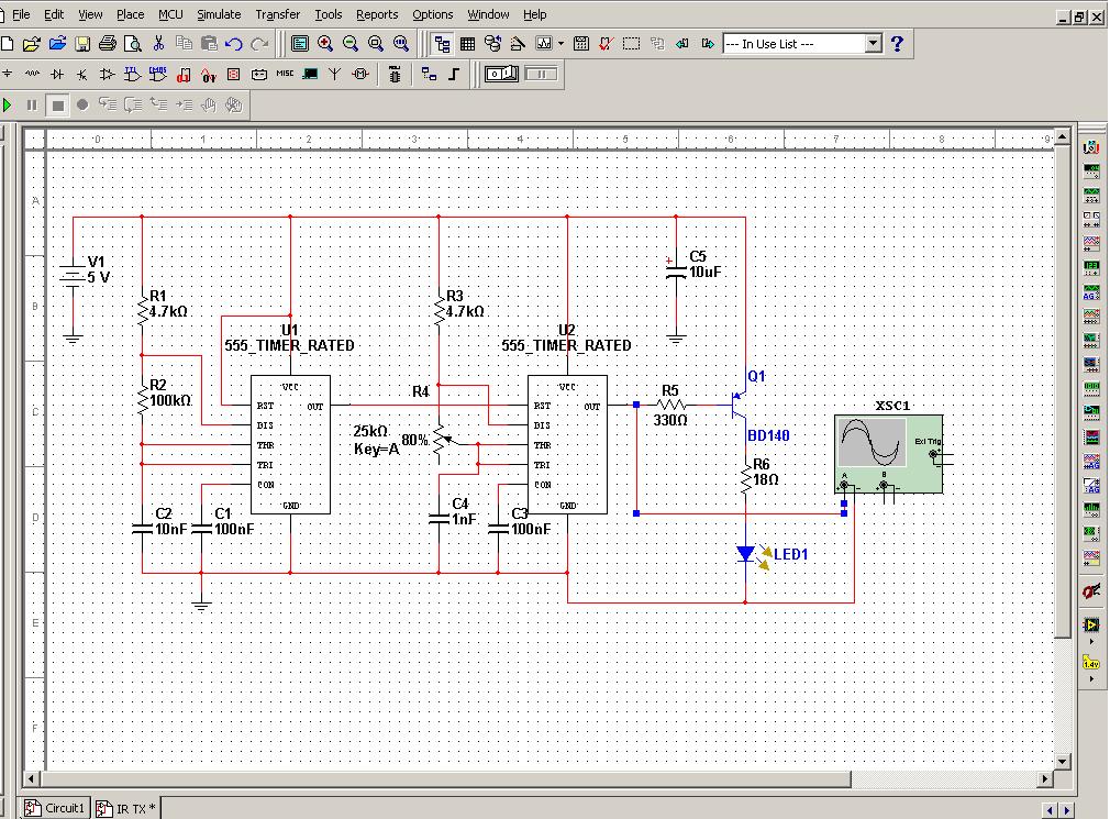
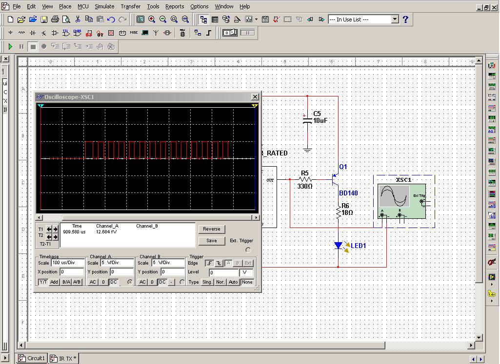
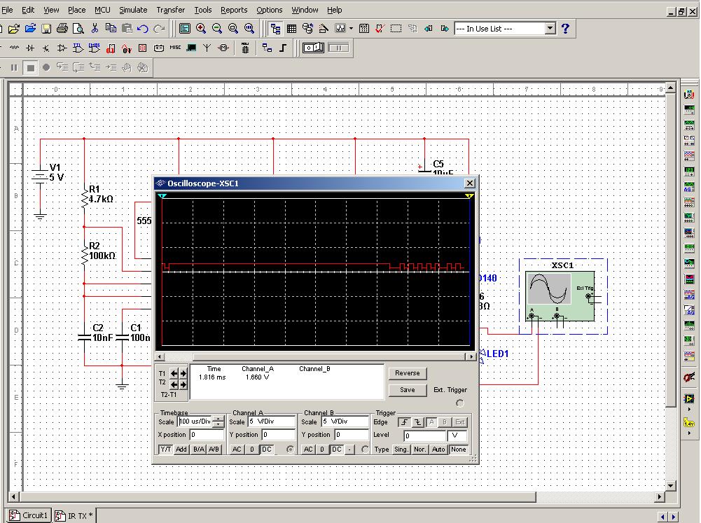
So far, what is in my mind is to use parallel to serial register IC to change into serial data, and modulate it using 555 timer. But I very unsure whether this is the correct way. If this is possible, what are the common IC available and how should the circuit look like:?: For receiving part, I will be using PIC16F877A microcontroller with IR receiver.

Another problem is how to make the robot stop like 1 meter before it reach the IR transmitter.

Pls give me your opinion. Ty.
 

The first problem is to let the 3 transmitted IR signals not to interfere each other at the IR receiver. Even their beam directions are different, there are always their reflections on the walls (or others) to be considered too. I mean do you think it is not a problem in your case?
 

The first problem is to let the 3 transmitted IR signals not to interfere each other at the IR receiver. Even their beam directions are different, there are always their reflections on the walls (or others) to be considered too. I mean do you think it is not a problem in your case?

By reduce the detection range, reflection from wall should also be reduced. So, I believe the main problem now is that the IR is transmitted concurrently, which mean they should have different bit pattern, like 11000001 for the first IR transmitter.
 

Ok, we will leave this possible interference problem for later.

Now, the easiest way (assuming the robot will receive, as you hope, one IR beam of the 3 transmitters) is to modulate the TX carriers with 3 different frequencies. This will be equivalent to sending 3 different patterns (continuously) as in the following example:

00001111… equivalent to frequency= F
00110011… equivalent to frequency= 2*F
01010101… equivalent to frequency= 4*F

So at the transmitter, you will need for example two 555; one for the carrier and one for the modulating signal.

Kerim
 

Thanks for your quick reply.

I found this schematic in following website, which I feel is suitable
Infrared alarm barrier

However, TSOP18 series of infrared receiver in their schematic is discontinued. So, is there other common type I can use?

Can you show me the formula to calculate the modulation frequency? I mean what is the electrical characteristic of IR receiver to decide suitable range of modulation frequency and duty cycle.
 
Last edited:

IR receivers are usually available in all markets and their exact name is not important as long they run on 5V. The IR carrier is likely 38 KHz but when you will have an IR receiver you can test its preferred carrier by noticing its sensitivity (to a continuous transmission) by varying the frequency (by a potentionter for example) of the 555 oscillator.

Added:
The upper modulating frequency is determined by the internal bandpass filter of the IR receiver IC.
Suppose you build a simple circuit using one 555 to generate 50% (actually it will be close to 50%) square wave signal (to drive the IR LED) in the frequency range 32 KHz to 44 KHz.

You will also build a very simple receiver circuit formed by the RX IR IC (that has 3 pins) and an LED with a series resistor to signal that the transmitted carrier is received. The LED anode will be connected to Vcc=5 and its cathode to a resistor (like 470 Ohm) which ends at the output pin (data) of the IR IC. By the way, you may need to discover which is the pin for ground, Vcc or data. I am afraid there is no universal standard for their number 1, 2 and 3.

Then you place the RX circuit at some distance from the TX one while you can see its signal LED. You will notice that in a band of about 4 KHz (from 32-44 KHz), the receiver LED will light.
Let us assume the lowest frequency is F1 and the highest one is F2. We can conclude that the IR carrier is:
F_carrier = (F1 + F2)/2
And at this distance the receiver can detect properly a modulating frequency if it is below:
F_max = (F2 - F1)/2
As you will notice F_max will decrease with distance, perhaps we will take advantage of this relation to determine approximately the distance. I have just thought about this now :wink: But this may not work if the design of the internal bandpass filter is flat well along the pass band and its attenuation roll-off is rather fast outside it. All this can be discovered while testing the real system.

Kerim
 
Last edited:
I expect the result should be square wave. But when I simulate the TX circuit here, I get distorted sine wave. Is it normal?
Infrared alarm barrier
 

I expect the result should be square wave. But when I simulate the TX circuit here, I get distorted sine wave. Is it normal?
Infrared alarm barrier

sine wave... voltage or current?... where in the circuit?

For instance, I use the free simulator LTspice. Which is yours?
 

Sry I made a mistake in circuit...The output of 555 timer now look fine. However, after pass through resistor and BJT, it gives a very weird voltage wave output.

I use Multisim.


Normal output from 55 timer.


Abnormal output from IR LED.

Let say selected modulating frequency is 400Hz, 200Hz, 100Hz,
Baud rate at RX is 800bps? The result is
1010 1010, 1100 1100, 1111 0000 or
0101 0101, 0011 0011, 0000 1111?
 
Last edited:

If the model of the BJT (PNP) or the model of the LED is not right then you will get something weird... is it possible to have a screen capture to let me have a better idea on what you see ... preferably the circuit and the trace.
 

I think the wave will be a square one and you should definitely trace it to remember it..
 

I don't see a weird output unless you mean the rather low voltage at the LED anode.
I am not sure which type of IR LED you will use for the real tests. But I like to suggest you change the values of R5 and R6 as:
R5 = 2.2K and R6 = 100 Ohm
The LED peak current would be about 35mA. Then when your project will work as expected and you need more power from TX you can easily lower the value of R5 and R6 again.

R6 = (Vcc - Vec - V_led) / I_led
R5 = A * (Vcc - Veb) / I_led

Vec (0.1 to 0.4) and V_led (1.2 to 1.6) varies bit with I_led (20mA to 120mA)
The constant A is Ic/Ib when the transistor is driven to be full on (Vce small) a typical value could be 20 (10 to 50).

Let say selected modulating frequency is 400Hz, 200Hz, 100Hz
I prefer talking about its period or interval in case in the future we will like to send 0's and 1's having different time intervals.
If F= 400Hz => T = 1/400 = 2500us , this mean that T_on= 1250us and T_off= 1250us
If F= 200Hz => T = 1/200 = 5000us , this mean that T_on= 2500us and T_off= 2500us
If F= 100Hz => T = 1/400 = 10000us , this mean that T_on= 5000us and T_off= 5000us

If you like to write a simple program, say as a test, and the IR receiver is assumed to receive one of the three signals, its edge interrupt routine will need just to read an internal running counter (likely 2 bytes), signal a new pulse is received (by a flag) and reset the counter before returning back to the main program loop. In the loop, the flag will direct the program to a subroutine to analyse the reading of the counter and to decide which TX is active (or none of the three) by updating the TX flags for example... etc.

If you will be able to pass this simple step then we will try to build a more sophisticated system though let us not forget that making a system to work reliably while being simple is the real challenge.

Kerim
 
Last edited:

I found a really cheap microcontroller to replace the 555 timer part of circuit, which is PIC10F202, I have PICKit2 programmer, but I couldn't find the programmer circuit to interface with the PIC. Pls help.
 

Sorry I have a little knowledge about PIC uC and their tools, I used to work with Atmel C51 series (or equivalent). But many here are surely familiar with such a programmer.
 

For RX part, is it suitable to use USART?
 

Whenever possible try to forget what others do to solve their projects.

I think you already have some knowledge on the devices you are using mainly the uC.
It was the same to me. So I usually tried (till now) to figure out what I can do as a solution using my acquired knowledge and skill (which are anytime too far from perfection). This helped me in two ways:

Revising and applying in a real project what are supposed I already know (hardware and software).
Finding the limits of my best solution.

One will be surprised that many points he thought they are well known and obvious to him, turn being not too clear when he fails in applying them the way he needs. But this is not bad. In fact, one can learn (I mean really learn) after failures only since it is hard to quit analysing something supposed to be clear and simple but refuses to work as expected. It will be like a personal challenge and not just an exam to pass.

You asked me if it is suitable to use the UART function in the uC.
On my side, I didn't find myself needing it, perhaps because I design my own protocols so that I can master them according to the application of interest both at TX and RX. The complexity of my protocols ranges from very simple to very complex but I didn't use UART yet. This was possible for me because ALL my designs are standalone (and specific) so I can't recommend it to other engineers.

Now for IR detection, the decision will be based for the RX side, on how the TX signal will be generated. If you look to use UART... both sides will have to satisfy the same conditions. You can do it if you like... but don't expect the system will work at the first test... In my case, if a new system I design could work properly after 100 updates I can see myself having a very good luck in this project :grin:
 
Last edited:

I cannot get the result from simulation.:sad:
At TX side, I make an signal w/o carrier frequency for simulation.

TX program to generate pulse:
txsimu.jpg
At RX side, I use USART with baud rate specified as around 3221 bps. I dunno what is going wrong, could be the logic or program is wrong...

Simulation:
**broken link removed**
Output should be 1 but it shows 0, as if no data is received.

RX program to receive pulse:
**broken link removed**

Or maybe u can show me your unique method. :wink:
 
Last edited:

I couldn't download your two attachements, their links seems to be invalid (as the pop-up messgae says)

Sometimes I believe that building a circuit is much simpler than simulating it :-?

As you know, we work on different tools, so we can exchange ideas only.

In any case, will you be able to build the circuit if the design is completed? For example the TX and RX parts in the least.
 

I have bought TSOP39438 IR Receiver. I have use your test method with LED and resistor and it works. Now I need to decode it with PIC microcontroller and here's next problem.

When I measure the Vout with multimeter,
When no IR light detected, Vout around 4.0 ~ 4.12 V
When IR light detected, Vout around 3.3 ~ 3.8V

Is this normal? Since I am sending ON OFF bursts from IR transmitter. So does that mean
V_OH = 4 V
V_OL = 2 V? approximately or lower??

I need to use analog comparator module of microcontroller to decode the signal or I can simply use digital input interrupt pin? If analog comparator is used, how do microcontroller know when it is rising edge or falling edge?
 

It depends on the duty cycle since the voltmeter will measure only the average voltage.
If TX sends a continuous carrier then the output should be close to 0V.
 

Status
Not open for further replies.

Similar threads

Part and Inventory Search

Welcome to EDABoard.com

Sponsor

Back
Top