Continue to Site

Welcome to EDAboard.com

Welcome to our site! EDAboard.com is an international Electronics Discussion Forum focused on EDA software, circuits, schematics, books, theory, papers, asic, pld, 8051, DSP, Network, RF, Analog Design, PCB, Service Manuals... and a whole lot more! To participate you need to register. Registration is free. Click here to register now.

Need help in HFSS using Driven Terminal for finding S-Parameters

Status
Not open for further replies.

Xeeshan143

Junior Member level 3
Joined
May 14, 2022
Messages
30
Helped
0
Reputation
0
Reaction score
2
Trophy points
8
Activity points
313
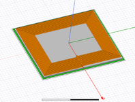
hello, I would like that. How should I find it in the HFSS using Solution Type (Driven Terminal)? I would also like to add the lumped RLC (by putting the capacitor value as in series). Also, i would like to add the excitation of current or voltage in the coil, as well as using lumped port in the rectangular sheet. but I am getting error during the simulation, I dont know where I am making a mistake, Please help me out in this problem
 

Attachments

  • figure11.PNG
    figure11.PNG
    93.4 KB · Views: 82
  • Driven Terminal.PNG
    Driven Terminal.PNG
    43.6 KB · Views: 80

As the simulation indicates, it's probably not a good idea to overlap the current source and a port - this might result in unexpected behavior. Also, the port should overlap the conductor to some extent -- it apparently is not. Ensure that the coil is set to a conductive material or has a conductive boundary condition applied.
 

As the simulation indicates, it's probably not a good idea to overlap the current source and a port - this might result in unexpected behavior. Also, the port should overlap the conductor to some extent -- it apparently is not. Ensure that the coil is set to a conductive material or has a conductive boundary condition applied.
Thanks for you Answer, The coil is a conductor, what is your opinion regarding to the Lumped Port and current as well as the RLC Lumped.
How should I give that value at the same time, because I would like to find out the S-paramenters and reduction of Current and voltage by putting the segments (Capacitors as in series in the Coil).

Your suggestion were be valuable thanks
 

what is your opinion regarding to the Lumped Port and current
I think I already stated this, they should not be overlapped. Set up two different simulations if you want to see the effect of either.

as well as the RLC Lumped.
An RLC boundary inserted in series with the coil on a surface is fine.

How should I give that value at the same time,
I'm not sure what you mean.

because I would like to find out the S-paramenters and reduction of Current and voltage by putting the segments (Capacitors as in series in the Coil).
You can measure current and voltage independently by inserting integration curves and using the field calculator.
 

Status
Not open for further replies.

Part and Inventory Search

Welcome to EDABoard.com

Sponsor

Back
Top