Continue to Site

Welcome to EDAboard.com

Welcome to our site! EDAboard.com is an international Electronics Discussion Forum focused on EDA software, circuits, schematics, books, theory, papers, asic, pld, 8051, DSP, Network, RF, Analog Design, PCB, Service Manuals... and a whole lot more! To participate you need to register. Registration is free. Click here to register now.

Need help in designing a 4-way wilkinson power divider

Status
Not open for further replies.

alard

Member level 4
Joined
Dec 2, 2004
Messages
70
Helped
4
Reputation
8
Reaction score
1
Trophy points
1,288
Activity points
551
4 way wilkinson

Hello,

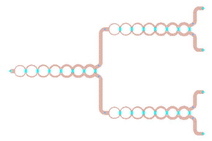
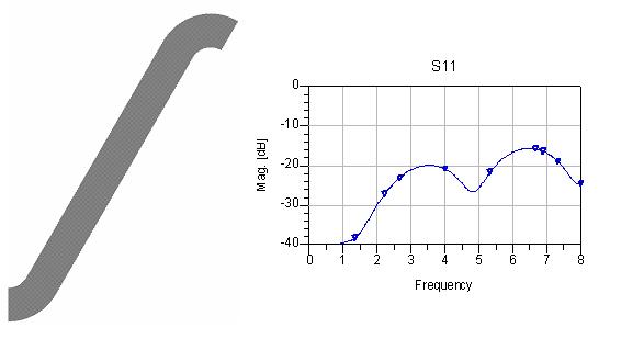
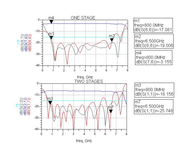
I've already finished designing a 2-way wilkinson power divider from 0.8 to 6.45GHz in microstripe technology. But I met problems when I am trying to cascade another two at each output ports with 50 ohms line to form a 4-way PD. The simulation results in Momentum and Microstripes are far from what I expected.

Could anybody share me some valuable experience? Some good references on this topic are also welcomed. :D Thanks in advance.

kevin
 

microstrip+4-way+wilkinson+power+divider

it is the same as 2 ports power devider that satisfies the match and power deviding
 

wideband wilkinson power divider

The only reason you would have problems is if the port return losses for your design were poor. What were the return losses?
 

wilkinsons designinga room

Hello Kevin,


Upload your ADS momentum or DXF files with substrate details so that it is easy to help or comment ...


---manju---
 

four-port wilkinson

Thx guys,

It seems the return loss, especially at the frequency above 6 GHz, is introduced by the bents of 50 ohms line. There's no problem if I directly cascade the PDs together.

The subsrate I am using is Er=6.15, H=1.542, T=35um, tanD=0.0018. Is there any way to improve it?

BR,
kevin
 

n-way wilkinson power divider analysis

hi,

maybe I'm wrong, but a wilkinson requires 70ohms lines which are lambda/4 in length to work properly. In the frequency bandwidth that you indicate (6GHz more or less), the deviation from the theoretical lengths will be very large, affecting the device behaviour.

I see that you simulate with momentum. probably you are also affected by some line-to-line coupling. some drawing of the circuit could be of help to analyse the problem.

regards
 

4-way wilkinson divider

dowjones said:
hi,

maybe I'm wrong, but a wilkinson requires 70ohms lines which are lambda/4 in length to work properly. In the frequency bandwidth that you indicate (6GHz more or less), the deviation from the theoretical lengths will be very large, affecting the device behaviour.

I see that you simulate with momentum. probably you are also affected by some line-to-line coupling. some drawing of the circuit could be of help to analyse the problem.

regards

For 2 port wilkinson needs using 70.7 Ohm line quarter wave trafo for transform between 100 input to 50 Ohm output (each leg, 100//100 Ohm give 50 Ohm on input) - and for wideband i think you must using some kind of multi section or tapered shape of quarter wave line. Shunt resistor between output port shall be 100 Ohm

for 4-port wilkinson you must make 200 Ohm - to 50 Ohm quarter wave trafo - 100 Ohm line quarterwave (each leg), and for wideband, same here, you possibly need some multi section or tapered shape of quarterwave line. Shunt resistor between output is a output impedance (50 Ohm) coupled in star together


Single stage quarter wave line in 2-port wilkinson have only around 1/3 octave bandwidth if you want return loss and isolation better than 20 dB on all ports.

single stage quarter wave line in 4-port wilkinson have 20 dB return loss limit on common input only to 1/6 octave, but return loss and isolation on output is now >= 1/2 octave

(bigger step quarter wave transform make bigger Q-value and smaller bandwidth)


If use 3 * 2-port single stage quarter wave line wilkinson to make 4-port give better bandwidth, worst is isolation between out port have 1/3 octave for 20 dB isolation limit.
 
wilkinson divider with bends

Ok, lets take this a step at a time.

If you cascade the 3 two-way splitters directly together they work well. If you then space out the splitters with 50 ohm lines with bends in them, they do not work well.

The conclusion is that the bends in your lines, or the width of the strip, or something else, is causing the two 50 ohm lines to not look like 50 ohms. So, use an analysis program to simulate the bends, and and microstrip line, and adjust the parameters until they are a good 50 ohm match to well above your operating frequency. For instance, you might have to chamfer the bends if they are right angle ones. You might want to make more gradual circular bends if you have the room.
 

4 way wilkinson power splitter

Thx Biff44,

I have attached the layout and the simulation of the 50-ohm line used as the connection of two power splitter. Finally I understand the the return losses come from the bents of both the inter-connection and the output ports.
94_1171876861.JPG

31_1171876803.JPG


Yes, I have tried to tune the length and width of 50 ohms line. However, it seems only the performance within 6Ghz has been changed meanwhile the return loss above 6GHz just slightly changed. To use an more smooth bent works better but will increase my size a lot. Now with the bents I show in the attachments. I got dimension of final layout around 119mm, which is quite close to the requirements(125mm with box) in the spcification.

biff44 said:
Ok, lets take this a step at a time.

If you cascade the 3 two-way splitters directly together they work well. If you then space out the splitters with 50 ohm lines with bends in them, they do not work well.

The conclusion is that the bends in your lines, or the width of the strip, or something else, is causing the two 50 ohm lines to not look like 50 ohms. So, use an analysis program to simulate the bends, and and microstrip line, and adjust the parameters until they are a good 50 ohm match to well above your operating frequency. For instance, you might have to chamfer the bends if they are right angle ones. You might want to make more gradual circular bends if you have the room.

Added after 9 minutes:

Also thank you very much xxargs,

Maybe I should consider to build a one-stage 4-way 'folk' power divider, which may avoid the annoying right angle bents.

Could you pls tell me more about how to design a multi-section n-way symmetric PD? I suppose it is the same as a 2-way PD (only 200 ohms instead of 100 ohms for the quarter wave transformer.) If so, then it will be impossible to relize a 157-ohm quarterwave length strip (W=0.04mm) for the first section in my case.

BR,
kevin
xxargs said:
dowjones said:
hi,

maybe I'm wrong, but a wilkinson requires 70ohms lines which are lambda/4 in length to work properly. In the frequency bandwidth that you indicate (6GHz more or less), the deviation from the theoretical lengths will be very large, affecting the device behaviour.

I see that you simulate with momentum. probably you are also affected by some line-to-line coupling. some drawing of the circuit could be of help to analyse the problem.

regards

For 2 port wilkinson needs using 70.7 Ohm line quarter wave trafo for transform between 100 input to 50 Ohm output (each leg, 100//100 Ohm give 50 Ohm on input) - and for wideband i think you must using some kind of multi section or tapered shape of quarter wave line. Shunt resistor between output port shall be 100 Ohm

for 4-port wilkinson you must make 200 Ohm - to 50 Ohm quarter wave trafo - 100 Ohm line quarterwave (each leg), and for wideband, same here, you possibly need some multi section or tapered shape of quarterwave line. Shunt resistor between output is a output impedance (50 Ohm) coupled in star together


Single stage quarter wave line in 2-port wilkinson have only around 1/3 octave bandwidth if you want return loss and isolation better than 20 dB on all ports.

single stage quarter wave line in 4-port wilkinson have 20 dB return loss limit on common input only to 1/6 octave, but return loss and isolation on output is now >= 1/2 octave

(bigger step quarter wave transform make bigger Q-value and smaller bandwidth)


If use 3 * 2-port single stage quarter wave line wilkinson to make 4-port give better bandwidth, worst is isolation between out port have 1/3 octave for 20 dB isolation limit.
 

4 way wilkinson

Why are there so many sections? You should be able to do the same thing with a two, or at most three section spitter.

The "circular" sections that you do show do not seem correct. The all seem to have the same "diameter", even though the impedance of the lines clearly changes. With the changing impedance, you will have minor changes in effective dielectric constant, which will require different line lengths (diameters) for the each section.
 

THX again biff44,

The reason I use 7 sections is that the extremely wide bandwidth in my case (0.8-6.45GHz). See my simulation result bellow. The first one is only one stage of a 2-way power divider and the second one is the result of three power dividers cascaded by ideal inter-connections. (not MLIN)
72_1171985393.JPG


Do you think there will be big difference of the radius? I calculated them through LineCalc in ADS. (from left to right r1=3.57mm, r2=3.72mm,r3=3.69mm, r4=3.67mm, r5=3.64mm, r6=3.61mm,r7=3.59mm)
 

Well, that is a big bandwidth (200%). I have done 160% with a 3 section.

The question is, what parameter are you interested in. If you only want to split the power equally, then 3 sections are all you need. IF you need good isolation betwenn the two output ports, then that might be the justification for so many sections.

Still, Try reducing it to 4 sections and see how it does.
 

    alard

    Points: 2
    Helpful Answer Positive Rating
Yup, Biff, it sounds a good idea!! I will be back soon.
 

hi friends
I want to design 120 way power splitter.
which configurations should i prefer.
I am new in this field.
 

Hi Biff44!

Yes, I finished the power divider with 4 sections. Now it has a much smaller size and fairly good perfomance. (Only the isolation is not as good as the PD with 7 sections. ) Now i am waiting for the simulation from Microstripes.

Anyway, thank you very much biff and other people who helped me in edaboard!!

biff44 said:
Well, that is a big bandwidth (200%). I have done 160% with a 3 section.

The question is, what parameter are you interested in. If you only want to split the power equally, then 3 sections are all you need. IF you need good isolation betwenn the two output ports, then that might be the justification for so many sections.

Still, Try reducing it to 4 sections and see how it does.
 

Sounds good.

As far as 120 watts, you can use the same type of splitter, but you need to be a lot more careful about how you implement things. Specifically, you will need:

A substrate that can conduct heat away from the transmission line, as it will get hot! The ground plane of the microstrip needs to be attached well to some sort of metal heat sinking surface.

The resistors in the splitter normally do not see any appreciable power. However, if one of the ports suddenly has a bad impedance (one of the amplifiers blowing up, and antenna icing up, etc), then all of a sudden the isolation resistors can see 60 watts of power! So the resistors need to be very high power ones, probably on a BeO substrate that is soldered to the housing floor.

You also have to be worried about signals arcing over. 120 watts gives a pretty high RF voltage, and if you use a thin substrate, there might be insufficient distance between the trace and ground at any edge.
 

I hope it's not 120W at 6.5Ghz... :roll:
 

And if you build for using in multi carrier system and high power, you must build for low passive intermodulation - is tricky enough in case 2x20 Watt GSM-carrier not make passive intemodulation higher than -130 dBm ( to not make lower sensitivity on GSM recivers if IM-products makes in recievers frequency range ) on passive equipment - it's common demand now for GSM-equipmet to pass 170 dBc to IM in case 2x20 Watt carriers.

GSM/UMTS equipment using mostly 7/16-connector in installation depend of above ie N-connectors not working trustfully enough in practical intallations...

---

I think you already disskuss and select good substrate with low loss, but I say again, do not try using FR4-substrate (for low price) in RF high power handling equipment, splitters and combiners - it's screaming IM in high power situation ( I learning this in hard way in multi carrier system... one piece on this 'shit' in wrong place can sinking whole system with drowned recivers depend of interference from passive Intermodulation... )
 

its not 120 watt
its 1 input 120 outputs (like multiplexer)
power is 1 watt
i want to feed power to 120 elements of antenna
so i need 120 way power devider
how should i design it .
please suggest me references & configuration to be used
 

Status
Not open for further replies.

Part and Inventory Search

Welcome to EDABoard.com

Sponsor

Back
Top