Continue to Site

Welcome to EDAboard.com

Welcome to our site! EDAboard.com is an international Electronics Discussion Forum focused on EDA software, circuits, schematics, books, theory, papers, asic, pld, 8051, DSP, Network, RF, Analog Design, PCB, Service Manuals... and a whole lot more! To participate you need to register. Registration is free. Click here to register now.

Need help in 4th-Order Source Follower Lowpass Filter design

Status
Not open for further replies.

JondorZ

Newbie level 3
Joined
Feb 10, 2011
Messages
4
Helped
0
Reputation
0
Reaction score
0
Trophy points
1,281
Activity points
1,311
Hi there,

I have a project to design a 4th-order source follower lowpass filter for medical applications. Here are the specifications:

1. Supply Voltage: 2.5V
2. Filter order: 4th-Order
3. Cutoff Frequency: 3kHz, 5kHz, 8kHz, 10kHz programmable
4. Power Consumption: <2mW
5. Design Tech: 0.35um CMOS


I am using Cadence Virtuoso to design and simulate the circuit. I am designing the circuit using NMOS, PMOS transistors, resistors, capacitors, and other relevant components. So I use the biquad design and it doesn't seem to be working. I need help in whether the biquad design is suitable or there is other better circuit design. Thanks a lot!
 
Last edited:
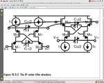
Some clarification seems to be necessary:
* "Source follower" means lumped transistor design rather than usage of opamps? (later you mention opamps);
* "Biquad design" is not unequivocal - perhaps you are referring to KHN or Tow-Thomas topology? However, some authors denote single opamp filter stages sometimes also as "Biquads".
* I would not recommend a two- or three opamp design for each 2nd order stage (because of power restrictions)

As you can see: If you ask for help you should give us information as much as possible (in your own interest).
 
I understand "source follower" as a synonymous of positive SAB (single amplifier biquad) with a gain of 1. Using a single transistor or an OP would of course affect the gain precision and thus the filter characteristic. For a "low Q", e.g butterworth filter, a small gain change won't matter much.

The intended method to get a programmable filter should be mentioned at least.The question is dedicated to IC design, so I fear, that a kHz frequency integrated filter most likely doesn't make any sense without external capacitors. Most designers would go for a switched capacitor circuit.
 
Thank you for the quick reply. Sorry for the vague description of my project.

Clarifications:
  • "Source follower" as in lumped transistor design, not opamp.
  • I have attached the "biquad" design I used.
  • The project only requires me to design the circuit schematic followed by layout design.
  • It is fine to use any external capacitors, resistors, or other components to help achieve the specs.
  • It is up to me to decide on how to design the programmable part, but i am not sure how to design it. Maybe you can give a suggestion? Thanks.

Please state if further clarifications are required. Thanks a lot.
 

Attachments

  • Biquad.png
    Biquad.png
    101.2 KB · Views: 92

Hi all, i need some help here. What is the difference between the opamp that is built on BJTs and opamp that is built on NMOS or PMOS? I have a schematic of BJTs inside the common 741 opamp from wikipedia (Operational amplifier - Wikipedia, the free encyclopedia) and i convert the BJTs to NMOS and PMOS. Can i do this? I am not sure how much width i should set for each of the CMOS transistor. Please help. thanks.
 

Hi, can somebody help me?? thanks in advance..
 

Status
Not open for further replies.

Part and Inventory Search

Welcome to EDABoard.com

Sponsor

Back
Top