Continue to Site

Welcome to EDAboard.com

Welcome to our site! EDAboard.com is an international Electronics Discussion Forum focused on EDA software, circuits, schematics, books, theory, papers, asic, pld, 8051, DSP, Network, RF, Analog Design, PCB, Service Manuals... and a whole lot more! To participate you need to register. Registration is free. Click here to register now.

Need Help: How to create comparator/op-amp logic for turning on LED

Status
Not open for further replies.

shmup

Newbie
Joined
Aug 24, 2021
Messages
2
Helped
0
Reputation
0
Reaction score
0
Trophy points
1
Activity points
43
Hello,
so I am having trouble with my project that professor tasked me with(This is not homework or something like that, I do not get any grades\points for this). I'm trying to design a primitive and basic circuit for "correcting" patients walk. Basically I plan on having 8 sensors in shoe that will read force measurement and give me somewhat equivalent voltage.Then I would use that voltage to find which sensor is most pressured and I would turn on the LED that corresponds the the most pressured sensor.In the assignment it's said that my sensors are FSR with positive resistance increase of 2kΩ/kg and that I would turn on only 1 LED unless there are 2 voltages that have values close to each other(+/- 10%) .This project has to be done in Analog, and I should mostly use op-amps and comparators.
So far I've created this current source so I could have linear force-to-voltage output.
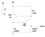
Sensors.png
My next step was to find the max voltage out of all and compare it to the voltage of the sensors and turn on the LED that matches the voltage.
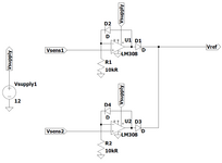
MaxVoltage.png
However my professor said that it's a bad idea and that op-amps would not be linear since they don't have feedback loop.He said I should be better of using comparators and instead of matching 2 or more voltages I should focus on difference between voltages.
My question is, how could find out which LED should I turn on using comparator/op-amps?
Any help would be much appreciated since this is my "intro" into Digital electronics!
 

Hi,

You're on a good way.

The idea with the current source is perfect for real pressure measurement.
But if you just want to find the "highest pressure" you may use simple resistors.

The approach with finding the highest voltage is good, too.

But there is a simpler way:
* individual Opamps are correct
* individual signal input to noninverting input is correct
* individual feedback diodes are correct.
* but connect all inverting inputs and use one resistor to GND only. Let's say R1.
* output diodes are not necessary.

What's happening:
* the voltage at the inverting input node shows exactly the max voltage of all sensors.
* the output of the opamp with max input voltage shows about (V_max + 0.5V)
* but all other Opamp outputs saturate at GND.
* so it's rather simple to find the channel with the highest pressure: it's the one with the output voltage not close to zero.

One could use individual comparators that activate a LED when input voltage >0.5V.

****
Even simpler:
Replace R1 with a 5mA current source. And replace the diodes with the LEDs. Done.

In detail it depends on the sensor voltage range and the Opamp supply voltages.

Klaus

Added: you need Opamp with high "differential input voltage range" and no "phase reversal".
 
Last edited:

Do you have to use basic parts as you mentioned or are you allowed to use a micro,
which by the way can do all this including the analog portion ? One with current
source, opamps, comparators, A/D, Vref, and decision handling....

I think this can all be done with one part, and a $ 10 board for dev.


Regards, Dana.
 
Last edited:

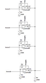
but connect all inverting inputs and use one resistor to GND only. Let's say R1.
Well I did that from the start but I just showed you a picture I use to describe how it works. This is the way it should look and there should be 4 more like it but it can't fit on a screenshot, all the components get blurry.Screenshot_3.png
After building this my idea was to feed the output to the comparators, compare this output voltage(Vout) to all the voltages from sensors and if they match I turn on the LED of that sensor.After that, I would take Vout and drop it down 10% of the original value and do the same thing by comparing it.Now even if this works it kinda seems like I'm using brute force to solve this and there must be a better way to solve it.
One could use individual comparators that activate a LED when input voltage >0.5V.
Wouldn't that just turn on any LED when any voltage goes above 0.5V or is that just for (Vmax + 0.5V)? I can't get this idea out of my head that IF Vout == Vsens THEN turn on the LED.
In detail it depends on the sensor voltage range and the Opamp supply voltages.
I don't think we should worry about the sensors at all since it has no meaning to me(it could be any sensor at all, only important thing is that it's resistance increases with the force), I only need to learn how to use op-amps and comparators. I'm not going to build this in a lab and it's not supposed to be too "realistic" problem.
--- Updated ---

Do you have to use basic parts as you mentioned or are you allowed to use a micro,
which by the way can do all this including the analog portion ? One with current
source, opamps, comparators, A/D, Vref, and decision handling....

I think this can all be done with one part, and a $ 10 board for dev.


Regards, Dana.
Well technically I can use whatever I want, and I could solve this using micro and digital or even Arduino, but I don't want to. I want to learn how to use Op-Amps and Comparators to "build my own Arduino" if you know what I mean.This project is designed to teach us how to use Analog Electronics to build anything we need.
 

Hi,
This is the way it should look and there should be 4 more
This is not the circuit I described. Mine is simpler and more accurate.
--> Mind my single common resistor for all inverting inputs.

Wouldn't that just turn on any LED when any voltage goes above 0.5V
No, with my circuit there is only one amplifier output >0.5V, all others are below.
I'm speaking for real circuits. With unrealistic ideal parts simulation you may get multiple to go above 0.5V.
Which from description in post#1 seems to be allowed.

I don't think we should worry about the sensors at all since it has no meaning to me
You have to set up the requirements.
We can't do this. We just can try to fulfill them.

Klaus
 
Last edited:

Status
Not open for further replies.

Similar threads

Part and Inventory Search

Welcome to EDABoard.com

Sponsor

Back
Top