Continue to Site

Welcome to EDAboard.com

Welcome to our site! EDAboard.com is an international Electronics Discussion Forum focused on EDA software, circuits, schematics, books, theory, papers, asic, pld, 8051, DSP, Network, RF, Analog Design, PCB, Service Manuals... and a whole lot more! To participate you need to register. Registration is free. Click here to register now.

Need Help: How to calculate input output voltage relation

Status
Not open for further replies.

atulk038

Newbie
Joined
Sep 11, 2020
Messages
2
Helped
0
Reputation
0
Reaction score
0
Trophy points
1
Activity points
16
Annotation 2021-08-11 115741.jpg

Hello,

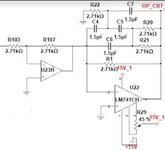
In the above circuit I want to know the output equation and wanted to know working of the given circuit
Supply Voltage - +15V to -15V
Vin = 2.5sin(2*3.14*400*t) V.
Thanks.
 

Hi,

When Vin > 0V then output saturates close to negative supply.
When Vin < 0V then output saturates close to positive supply.

All the feedback circuitry is about useless.
Read about "inverting Opamp circuit operation". It needs an input resistor to work properly.

Please use one of the free simulation software to check circuit operation.

Klaus
 

Hi,

Still missing the input resitor to U22.

Now you have an inverter in front of the circuit above...
Thus:
When Vin < 0V then output saturates close to negative supply.
When Vin > 0V then output saturates close to positive supply.

Klaus
 

Hi,

Oh yes, true.
I did not read the values yet. But they really make no sense.
Neither the rediculously low 1.5pF nor the non_standard 2.71k.

It´s no practically meaningful circuit.

Klaus
 
For a first estimation, the OP will work as comparator. Output waveform is a 400 Hz square wave. You can omit all R and C and get approximately the same output with the 2.5 V sine input.
 

Status
Not open for further replies.

Similar threads

Part and Inventory Search

Welcome to EDABoard.com

Sponsor

Back
Top