Altafhal
Member level 2
error in pic programmer
Dear friends
I am working on my final year project in which i am using pic16f877a microcontroller.
I have build a programmer ezpic which scematic i have downloaded from sunrom which i have attached with
thisthread.
I build the pcb and test it with 16f877a. i am using icprog for programming the chip.
But every time when the programming is finished i got an error saying that vrify failed, the image of this error is also attaced.
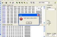
I have P4 computer and using windows XP. I also suffer this error on windows 98 and also when i have programmed 16f84a.
and when i use the programmed controller it gives no response.
I need your help about
1) What is that error and its cause?
2)i have connected the ICD connector pins with SW1 pins respectively ie pin1 with pin1 and 2 with 2 and so on, is it correct?
3)Is there any other programmer which i can use if yes then plz anyone can give me its schematic or pcb?
I have found a very simple programmer at a forum which is in text format as followed
""TXD (3) ------[4.7k]-------VPP
GND (5) --------------------VSS
DTR (4) -------[4.7k]------DATA
CTS (8) ------------------DATA
RTS (7) -------[4.7k]------CLK
Numbers in Bracket are the connections on the 9-Pin D-Connector.
Then just put your PIC into a breadboard, connect your 5 volt supply to VDD/VSS, and away you go.""
but when i build the above programmer the same error was occured.
Plz i need urgent help.
Thanks.
Dear friends
I am working on my final year project in which i am using pic16f877a microcontroller.
I have build a programmer ezpic which scematic i have downloaded from sunrom which i have attached with
thisthread.
I build the pcb and test it with 16f877a. i am using icprog for programming the chip.
But every time when the programming is finished i got an error saying that vrify failed, the image of this error is also attaced.
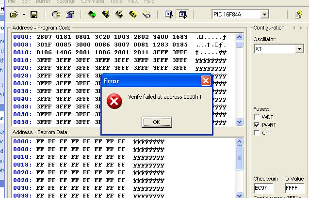
I have P4 computer and using windows XP. I also suffer this error on windows 98 and also when i have programmed 16f84a.
and when i use the programmed controller it gives no response.
I need your help about
1) What is that error and its cause?
2)i have connected the ICD connector pins with SW1 pins respectively ie pin1 with pin1 and 2 with 2 and so on, is it correct?
3)Is there any other programmer which i can use if yes then plz anyone can give me its schematic or pcb?
I have found a very simple programmer at a forum which is in text format as followed
""TXD (3) ------[4.7k]-------VPP
GND (5) --------------------VSS
DTR (4) -------[4.7k]------DATA
CTS (8) ------------------DATA
RTS (7) -------[4.7k]------CLK
Numbers in Bracket are the connections on the 9-Pin D-Connector.
Then just put your PIC into a breadboard, connect your 5 volt supply to VDD/VSS, and away you go.""
but when i build the above programmer the same error was occured.
Plz i need urgent help.
Thanks.