Continue to Site

Welcome to EDAboard.com

Welcome to our site! EDAboard.com is an international Electronics Discussion Forum focused on EDA software, circuits, schematics, books, theory, papers, asic, pld, 8051, DSP, Network, RF, Analog Design, PCB, Service Manuals... and a whole lot more! To participate you need to register. Registration is free. Click here to register now.

Need help about burning scooter board

Status
Not open for further replies.

necroshine83

Newbie level 4
Joined
Nov 25, 2020
Messages
6
Helped
0
Reputation
0
Reaction score
0
Trophy points
1
Activity points
71
Dear forum user,
I am new at this forum. I need some help about the electric scooter board which is as similar as i try to post here. The problem is, there is a fault scenario like that: when my child driving the e-scooter motor suddenly behave like full throttle. At this point, i can't make the e-scooter stop. The only solution is disassemble the battery pack or motor.

I tried some workarounds. I made 2 mosfets in parallel and attached them on to a copper laptop cooler. it survived a while but same issue happened.

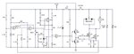
The only difference my original circuit:
I dont have D1 diode and 2.4k resistor paralel to hall sensor.
My main capacitor is 220uF 50V
I have 1 mosfet irfz44, there was a burn resistor which i measured aroun 1/8 watt 1.46k between transistor out and mosfet in. I replaced them with 33 ohm 1/4 watt resistor. What does it do?
There is an extra 100k resistor between + of the comparator1 and ground.
I replaced 2 x12V acid battery with 25.2 lithium ion battery, so main voltage is 25.2 volt at full charge.
 

Attachments

  • escooter_circuit schema.jpg
    escooter_circuit schema.jpg
    119.6 KB · Views: 241
  • WhatsApp Image 2020-11-25 at 15.29.48.jpeg
    WhatsApp Image 2020-11-25 at 15.29.48.jpeg
    73.3 KB · Views: 220
Last edited:

Questions:

1.
J1 J2, are they for circuit protection? Fusible links? Wires that evaporate if current gets too high? Did they go bad previously at any time?

2.
LM339 is a popular comparator IC (4 on one chip). A comparator's output provides either a path to ground or high impedance. There's a question whether it can fully turn on Q3.

Did you test Q3 as good? Its supply is 24V, however it receives bias 12V from the resistor divider. Or else IC2 pulls bias to ground. To turn on fully Q3 needs bias 24V.

If Q3 turns on partially there's a chance the mosfets only turn on partially. This causes the mosfets to heat up greatly which may cause their innards to fuse and pass maximum current (resulting in your runaway problem).

The mosfets are suppose to turn fully On and fully Off rapidly. That is the common practice to achieve best efficiency (assuming this circuit is designed for efficiency).

3.
Q4 is PNP type. Its icon is upside down in the schematic although it's probably oriented properly on the hardware. Can you confirm its base-emitter-collector terminals?
 
Dear Brad,

Thank you for your answer.
Jp1 and JP2 are not fusible links. You can see it in original picture above, just upside of the green cable.
I do some workaround: if the zener diode go shorted or if you remove zener and its resistance in series; the output of the comparator2 gives 12V and this makes motor run at %100.

Edit:
i replaced zener diode with 5watt zener. Circutry is working normally now. Of course i will not stop searching same thing can happen again.

Let me check if Q3 turns on fully, but since i am not an electronic expert, how can i do this?
LEt me check Q4 is connected correctly.

How about 33 ohms resistances? What do they do? If i replace them with 1.5k resistor motor will run faster. If i put 33 ohms motor is running very slow.
And how about diode in hall sensor ? I dont have this diode. What does it do should i add it to my circiutry?

thanks,

Onur
 
Last edited:

Let me check if Q3 turns on fully, but since i am not an electronic expert, how can i do this?

It probably gets a bias signal switching on and off rapidly, too rapidly to measure changes in voltage across it. Instead a convenient method is to apply bias from a potentiometer, at various volt levels, briefly and see how high bias voltage needs to get in order to run the motor at full speed.

How about 33 ohms resistances? What do they do? If i replace them with 1.5k resistor motor will run faster. If i put 33 ohms motor is running very slow

Schematics posted here commonly have resistors in the bias wires to mosfets (despite the extremely high resistance of their insulated gates). It appears to be among the finer details of operation which professionals pay attention to.

And how about diode in hall sensor ? I dont have this diode. What does it do should i add it to my circiutry?

Is that a hall sensor next to the motor? (I don't know about the diode.) The hall sensor may be for circuit protection. If the motor stalls it draws extreme current, with risk of burning up windings. Good design strategy senses this extreme current and makes the control circuit shut off the motor. It does not necessarily sense normal current therefore it did not stop your runaway motor.

Logically the 'On' switch ought to be installed at the battery. Is it really located so the motor continually gets supply voltage? If you relocate it that would easily let you shut down a runaway motor.

I'm not certain as to functioning of the switch and diode marked 'brake'. Perhaps it performs quick braking of the motor.
 

I just measured 2.5V max from the hall (throttle). It means around %50 duty cicycle of the PWM. How can throttle give 2.5V at full? It should be 4V!
 

Dear Brad,

2.
LM339 is a popular comparator IC (4 on one chip). A comparator's output provides either a path to ground or high impedance. There's a question whether it can fully turn on Q3.
Q3 is drived with 12V from the IC output. I could not identify if fully or partially. But i corrected my hall sensor. It is sending IC nor between 1-4V as it should be. And comparetor output is 0-12 V.
3.
Q4 is PNP type. Its icon is upside down in the schematic although it's probably oriented properly on the hardware. Can you confirm its base-emitter-collector terminals?
Yes they are connected as the schema shows, double checked.

Logically the 'On' switch ought to be installed at the battery. Is it really located so the motor continually gets supply voltage? If you relocate it that would easily let you shut down a runaway motor.

Yes, i am planning to add a emergency button which immediateley shuts down the motor. But is there a electronic trick that i can add to my circiutry?

Now i have couple of questions:

1. There is a scnerio if the zener dioed gets shorted sytem bypasses switch and gives battery output directly(runaway problem). How can i prevent this.

2. What do the diode serve connected to the brake switch, should i add it ?
I'm not certain as to functioning of the switch and diode marked 'brake'. Perhaps it performs quick braking of the motor.
Brake is mechanical, there is a button which send signal to IC (inhibit) and shutdown the transistor input. But as i told this is not working when the zener gets shorted.
 

I just measured 2.5V max from the hall (throttle). It means around %50 duty cicycle of the PWM. How can throttle give 2.5V at full? It should be 4V!

Yes, 2.5 V is expected reading when switching 5V @ 50 % duty cycle (motor going half speed).

A hall sensor usually reads half of supply V when idle or when sensing alternating north and south poles at high speed. I think it's similar with a hall switch too.

Duty cycle and current draw are different when the scooter carries a 100 lb. human, compared to when you run tests on it unloaded.

Can you get readings at the node between Q3 Q4 & 33 ohm resistors, at various speeds? It should give a clue as to duty cycle. And probably let you know if Q3 operates correctly.

1. There is a scnerio if the zener dioed gets shorted sytem bypasses switch and gives battery output directly(runaway problem). How can i prevent this.

You replaced the zener with a 5W rating. This should be adequate to endure the amount of current coming through the 500 ohm resistor @ 24 V.

Does the 500 ohm resistor ever get hot? If 48 mA (calculated) goes through it, then it dissipates 1W of heat. It starts to burn fingers pinching it.

2. What do the diode serve connected to the brake switch, should i add it ?

When a component's purpose is not obvious then it may be included to perform circuit protection... due to reverse voltage, static charge, voltage greater than 5V going to IC inputs, perhaps.
 

Does the 500 ohm resistor ever get hot? If 48 mA (calculated) goes through it, then it dissipates 1W of heat. It starts to burn fingers pinching it.

Yes it is very hot. I have an idea to replace the zener with 5V regulator. Do you suggest such an action?

Can you get readings at the node between Q3 Q4 & 33 ohm resistors, at various speeds? It should give a clue as to duty cycle. And probably let you know if Q3 operates correctly.

well, i have no equipment to do this so.

I fixed the HALL sensor, it was giving 2.5 when @ maximum throttle. After repair, maximum voltage is around 4V az expected.
 

Status
Not open for further replies.

Part and Inventory Search

Welcome to EDABoard.com

Sponsor

Back
Top