Welcome to our site! EDAboard.com is an international Electronics Discussion Forum focused on EDA software, circuits, schematics, books, theory, papers, asic, pld, 8051, DSP, Network, RF, Analog Design, PCB, Service Manuals... and a whole lot more! To participate you need to register. Registration is free. Click here to register now.
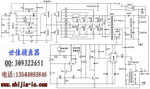
I need explanation of the attached circuit schematic. What is the purpose of D1, D2 and T1. This circuit is used in electric fishing. i generated high voltage pulse at 30 to 100Hz rate with variable duty cycle.
Fish murderer! That is probably the least Eco-friendly device I've ever seen.
D1 and D2 are to conduct a high voltage, high current pulse to T1 which steps it up approximately three times higher in voltage. They are SCRs, a kind of diode that needs switching on and stays on until the voltage across it is removed. When triggered, D1 dumps the high voltge into T1, then after a short period, D2 reverses the voltage across D1 to stop it conducting again. It's called "commutation". Keep fingers WELL AWAY from that thing, it can easily kill people as well as fish.
"When triggered, D1 dumps the high voltage into T1, then after a short period, D2 reverses the voltage across D1 to stop it conducting again. It's called "commutation"."
what is the function of secondary side of T1?
- - - Updated - - -
High DC Voltage is present at point B of D1.
When D1 is turned on Dc voltage are applied to the transformer T1 and are available to the load point (a small circle). How voltages are amplified at this point? is there any flyback/ back emf action?
What happens at the secondary side during D1 turn on time?
How D2 reverses the voltage across D1 to stop it conducting again?
Either Adnan012 understands the circuit or they shouldn't be using it. In this case, a lack of knowledge could have disastrous consequences, including loss of life of more than one person.
Adnan012, please don't use it for your own sake. It is VERY unsafe and if you have one that has failed, it should be returned for professional repair. Personally, I think this kind of device should be banned Worldwide.
This site uses cookies to help personalise content, tailor your experience and to keep you logged in if you register.
By continuing to use this site, you are consenting to our use of cookies.