Continue to Site

Welcome to EDAboard.com

Welcome to our site! EDAboard.com is an international Electronics Discussion Forum focused on EDA software, circuits, schematics, books, theory, papers, asic, pld, 8051, DSP, Network, RF, Analog Design, PCB, Service Manuals... and a whole lot more! To participate you need to register. Registration is free. Click here to register now.

Need circuit idea for light sensor.

Status
Not open for further replies.

Ignas Pranckevi

Newbie level 3
Joined
Sep 22, 2014
Messages
4
Helped
0
Reputation
0
Reaction score
0
Trophy points
1
Activity points
32
output protection.pngoutput protection.pngHello I need advice for my solar tracker system. I'm trying to create light sensor using LM358 OA and LED sensor diode. I use controller measurement light signal. I use controller Atmega32 which I connected with OA output (with ADC port). I protect it from high voltage signal with SD. So I want to get a range between 0 - 3.3 V from light sensor. My solar signal must to depend from light intensity of days. I add my project circuit above but it's not correct. Actually I don't know what is wrong with my circuit because I'm getting 0.7 V signal when is dusk and 0.7 when is dark. :( So it's not tolerated for this. Of Course I get correct signal if light intensity is much stronger signal that dusk or dark.
https://obrazki.elektroda.pl/9822506800_1430645844.png
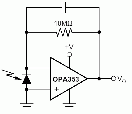
 

Not sure which sensor you are actually using, 02BZ2.2 is a zener diode. Presumed it's any kind of photodiode (or a LED used as photo diode), you can expect better results when operating the diode in zero voltage bias than in photo element mode. See the below circuit as an example.

90_1248513477.gif
 

Hi,

Yes, FvM is amplifying current, while your circuit is amplifying voltage.

For photodiodes the current is about proportional to light density, the voltage is far from being proportional.
Voltage -with no load - is soon at a specific level and changes not that much after that...

LEDs may be used as light sensor, but why not using a standard photodiode? The output signal is much higher and predictable/calculable.

Klaus
 

Hello. Actually I used a simple LED diode, after I used photodiode and I compared a both. Now I'm using photodiode. Yes you are right for zener diode there was really zener diode. I have a several issue, why do you use in this example OPA353? Perhaps its debends something from it? What's nominal of capacitor?
 

As said it's just an example circuit. You can use LM358 as well. Don't necessarily need a capacitor with slow OPs. The resistor has to be adjusted to the application, so that you get full scale output at maximum irradiance.
 

Hi Klaus. Originally I tried with LED and I saw that wasn't a good result which I want to get. After I tried with a photodiode, of course the result is was far batter comparing with LED. At now I'm working with photodiode but result is not accurate for dusk and dark.
 

Hi FvM. I tried your example, I think it works but this is very sensitive. Parhaps you can advice me for sensitive, how to reduce it?
I put on several capacitor 68 nF between OA Output and Negative but nothing changes for it.
 

Status
Not open for further replies.

Similar threads

Part and Inventory Search

Welcome to EDABoard.com

Sponsor

Back
Top