Continue to Site

Welcome to EDAboard.com

Welcome to our site! EDAboard.com is an international Electronics Discussion Forum focused on EDA software, circuits, schematics, books, theory, papers, asic, pld, 8051, DSP, Network, RF, Analog Design, PCB, Service Manuals... and a whole lot more! To participate you need to register. Registration is free. Click here to register now.

Need circuit help in a normal five voltage input and output system.

Status
Not open for further replies.

Puneet Kaushik

Newbie level 5
Joined
Aug 18, 2015
Messages
8
Helped
0
Reputation
0
Reaction score
0
Trophy points
1
Activity points
72
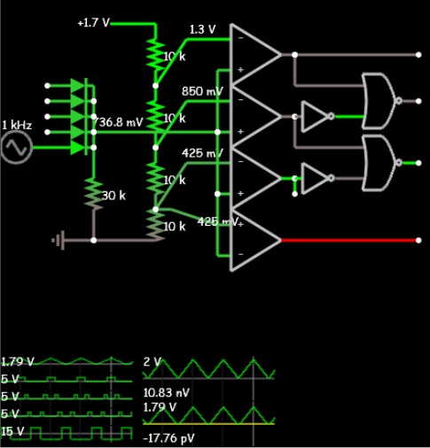
Need a circuit help in normal five voltage input and five ouput system.

My idea is to give in five different input and take them individually without effecting each other. All are simple voltage input in varying in nature according to resistance change. What method do you guys suggest for this circuit implementation. I need minitaure because it is part of wearables. Please suggest me if it can be possible without using a microcontroller.

Thanks
Life is sharing and caring
 

Re: Need a circuit help in normal five voltage input and ouput system.

You forgot to mention the intended relation between in- and ouput signals, respectively the function of your system.
 
Re: Need a circuit help in normal five voltage input and ouput system.

Hi,

.. and all values. Like voltage range, current, frequency....

A schematic could help also.

Klaus
 
Re: Need a circuit help in normal five voltage input and ouput system.

Blue print.png

Here i attach a image. Pelase have a look.

Thanks
 

Re: Need a circuit help in normal five voltage input and ouput system.

Doesn't that mean INPUT = OUTPUT....?
So what's the need of a circuit there?
 
Re: Need a circuit help in normal five voltage input and ouput system.

Hi,

without current flow there is no voltage drop in resistor (R1 ... R5). So it seems they are useless somehow.

You have 5 inputs on your box left side. Are they high ohmic voltage sensing inputs? With an input range of 0...5V?

On the right side there are 4 outputs. Your description seems that there sould be LEDs. Is there one LED at each output = 4 LEDs in total?

Klaus
 
Re: Need a circuit help in normal five voltage input and ouput system.

I am really unable to explain what i am looking. Can you help me to find a smd which give multiple output

Example

input is one but it varies over range 0.0 to 2.0 V

Condition for selecting output
when input is 0.0 - 0.5 V than it will select output no 1
when input is 0.6 - 1.0 V than it will select output no 2
when input is 1.0 - 1.5 V than it will select output no 3
when input is 1.5 - 2.0 V than it will select output no 4
 

Re: Need a circuit help in normal five voltage input and ouput system.

Hi,

it is really hard to help, when you are not able to explain.

Maybe what you need is a "4 Channel Multiplexer", like ADG604:
You have 4 analog signal inputs (maybe audio sources like MP3, cellular phone, Mp3 plxyer..) and one output (maybe to amplifier --> speaker)
With A0 and A1 you can choose one of four sources. These are digital inputs. 0 or 1 (Low or high). With the EN pin you may switch OFF all inputs.

****
Please describe:
* Where do the signals come from?
* Where do the signals go to?
* What´s youridea behind that all?
I´m sure you know all that. If you need help, give us the informations.

Klaus
 
Re: Need a circuit help in normal five voltage input and ouput system.

what if input < 0 or > 2V?
Use 0.2V Diode OR logic analog input so highest voltage is detected, then

All you need is four Window detectors with 3 comparators and logic to gate when Vin > Vx and Vin < Vy

Or use LM3914 with 10 levels and active low side driver/selector out.
Offset input by 1 Diode drop to 0V then calibrate to your thresholds and use 5 outputs with Priority Decoder IC.

Or better do all in 1 PLD.
 
Re: Need a circuit help in normal five voltage input and ouput system.

hello


look at LM3914 Analog input ---> 8 led segments output
or this kind of application
**broken link removed** : 11V to 14V -> 6 leds ... to adapt to your range
 
Re: Need a circuit help in normal five voltage input and ouput system.

Unbenanssnt.PNG

i made this with help of LTSpice. But at all LED output are same. I can not tune it for input variation. I am new to LTSpice so pelase help me find out anz problem in circuit or simulation data. I want to simulate data so i can have different range of input (example 0-3 due to resistance change at input via whistone bridge). And for particulaar range of input i can have either1 or 2 or 3 or 4 or 5 led working.
 

Re: Need a circuit help in normal five voltage input and ouput system.

The resistor values and LM3914 wiring make no sense. Presently the programmed input voltage range is about 0.8 to 1.2 V, with only mV input voltage.
 

Re: Need a circuit help in normal five voltage input and ouput system.

Choose V_hi and V_lo to match the max,min voltage of your bridge.

If too small , then boost signal to be 0~1.25V
LM3914 LED bar.jpg
 
Re: Need a circuit help in normal five voltage input and ouput system.

pressure sensor.PNG


This is mz pressure sensor behaviour. I am using 3.3 volt batterz. I need output of mz sensor part 0.5-3.0 voltage. Is it possible using wheastone bridge. I am trzing this. But values of resistor is not supporting me to get a desired range. Can you guys help me to find a proper wheastone bridge to have output 0.0-3.0 volt. I need these valuse for LM 3914 which i have realise for 0-3 volt input.....


Thnaks
 

Re: Need a circuit help in normal five voltage input and ouput system.

The curve defines the sensor behaviour, but doesn't tell how you want to map force or resistance to voltage. Please clarify.
 

Re: Need a circuit help in normal five voltage input and ouput system.

Can you guys help me to find a proper wheastone bridge to have output 0.0-3.0 volt.

An op amp's two inputs are easy to configure as a wheatstone bridge. It is a common way to hook up a sensor.

See my post #4 in the thread:

https://www.edaboard.com/threads/343675/

My schematic has a fixed resistor (33k) above the sensor. You should substitute a potentiometer. Experiment to find suitable settings, which provide the output you want.
 

Re: Need a circuit help in normal five voltage input and ouput system.

Unbenannt.PNG


can i use my sensor like this. I have 20K resistance at signal pin of IC. I have tried your waz too but, constraint is input voltage and i can not use more than 3V. you are using opamp and i need to make it so small that i must avoid many stuff at my pcb.

i have attacched only sensor part of circuit. when i simulate it. it works as per next picture. But i am not sure that is it a correct way...

Unbenannt.PNG

- - - Updated - - -

Can i use simple voltage divider for my sensor part to have 0- range
 

Re: Need a circuit help in normal five voltage input and ouput system.

The LM3914 is easy to make the first output active when the input is 0V to 0.5V, the second output active when the input is 0.5V to 1.0V, the third output active when the input is 1.0V to 1.5V, the forth output active when the input is 1.5V to 2.0V and on and on like that.
The reference pin 7 is 1.28V when the ADJ pin 8 is at ground and a voltage divider is used similar to an LM317 adjustable voltage regulator to increase the regulated output voltage so that a resistor to ground from the ADJ pin 8 and another resistor from the REF pin to the ADJ pin sets the reference voltage at 3.0V which is connected to Rhi pin 6. Rlo pin 4 is connected to ground.
The LED brightness is set by the amount of current at the REF pin.
 
Re: Need a circuit help in normal five voltage input and ouput system.

Can i use simple voltage divider for my sensor part to have 0- range

The 3914 IC is suitable, but first you must do some experimenting, to figure out what range of input voltage it requires, and to find out how to adapt your sensor to that range of voltage.

You may need to reverse the sensor and resistor. Etc.

Or, you may need to amplify the sensor output. Etc.

The 3914 has a pin for applying a reference voltage. This may provide a means to adjust your operating range.
 
Status
Not open for further replies.

Part and Inventory Search

Welcome to EDABoard.com

Sponsor

Back
Top