scream_er
Member level 5
Hey guys,
I need a simple low power, high gain pre-amplifier circuit for an electret microphone. I have come across two pre-amplifiers, which are attached. Which one would most idle considering its simple, high gain and low power?
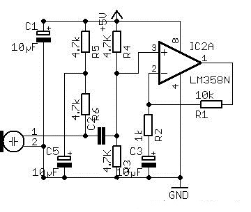
CIRCUIT 1

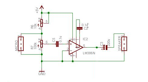
CIRCUIT 2

I need a simple low power, high gain pre-amplifier circuit for an electret microphone. I have come across two pre-amplifiers, which are attached. Which one would most idle considering its simple, high gain and low power?
CIRCUIT 1
CIRCUIT 2