Continue to Site

Welcome to EDAboard.com

Welcome to our site! EDAboard.com is an international Electronics Discussion Forum focused on EDA software, circuits, schematics, books, theory, papers, asic, pld, 8051, DSP, Network, RF, Analog Design, PCB, Service Manuals... and a whole lot more! To participate you need to register. Registration is free. Click here to register now.

Need A Help(Light Dimmer and Fan Regulator)

Status
Not open for further replies.
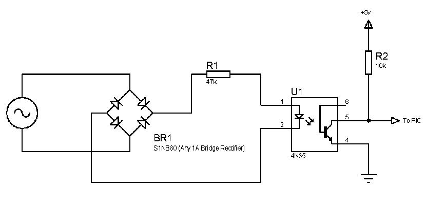
Hi, the transitor their is an NPN transistor therefore it can only conduct during the positive have cycle making the collector out of phase with the base of the transistor.
 

hi,

it will work with out microcontroller

what is the use of zerocrossing without a microcontroller.

I feel you are not clear about what you are doing. First define precisely what you need.
 

Hi,
It's similar in principle to what I posted, just offers isolation and so safer.

It works like:

Near about the zero crossing period, the output at the collector is 1, and at other times, the output is 0. So use your microcontroller to check for 1. If 1 at collector is sensed, that means, that it's crossing the zero crossing period, otherwise, if 0 is sensed at collector, its means that you're not at the zero crossing point.

When there is no zero-crossing, the voltage is stepped down, rectified and turns the transistor on, causing 0 at collector. However, during zero-crossing, there is 0v at secondary, the base is off. The transistor is off and the capacitor supplies +v.

Hope this helps.
Tahmid.

---------- Post added at 14:00 ---------- Previous post was at 13:56 ----------

hi,

it will work with out microcontroller

Yes,
That's because zero-crossing detection isn't done (not usually) with the microcontroller. It is done by a circuit that works without microcontroller. The microcontroller uses this signal for thyristor control. The zero-crossing detection is a circuit that works independent of the microcontroller, providing an output signal either 1 or 0 for the microcontroller depending on the state of the AC mains input, either 0 for zero-crossing and 1 at all other times or vice versa.

Hope this helps.
Tahmid.
 

Hi,

thanks for the mail i have the ZCD circuit and it is working fine.

I have made the Triac On using Microcontroller 8052 but i dont know how to turn off the Triac .Please help me out for the Same.
 

Hi friend,

Hi,

thanks for the mail i have the ZCD circuit and it is working fine.

I have made the Triac On using Microcontroller 8052 but i dont know how to turn off the Triac .Please help me out for the Same.

Wheneve AC Line cross Zero voltage, Triac will automatically off.

Triac should be ON by gate Signal, but it will off automatically by itself.

Regard,
Shyam
 

Hi ,


I have tried but it not automatically turning off . It is in continous on posittion


help me
 

Hi,
Okay, I've seen something similarly weird happen. If you're not using MOC3021, then, place a 10nF capacitor between the gate and transistor or gate and whatever's driving it.

Hope this helps.
Tahmid.
 

Hi friend

Please, Upload your schematic, then I will help you properly.

I have already done this project,
Using IR remote control, it turn ON/OFF six Lamps and two Fan speed variation.

I have already manufacturing this product and sell.

Please, Specify, what is your requirement and what do you want.

Regard,
Shyam.
 

Hi Shyam,
I am trying to make something similar with 2 turn on/off lamps and 1 fan speed variation.
I am doing the fan speed variation with pulse skipping. How did you do it? Pulse skipping or phase control?
I am trying to fire the triac but I'm failing. How do I fire a triac directly from microcontroller with Triac MT1 connected to live and load between MT2 and neutral?
 

hi,


i have connected the triac with Optocoupler MOC3021 . and MOC3021 input is connected to Micocontroller 8052.

Light turns on when miicrocontroller send a +5v signal to optocoupler and triac trigger,but what is the procedure to turn off the triac

---------- Post added at 09:59 ---------- Previous post was at 09:54 ----------

hi,shyam,

As you have already done this project please let me know ,the circuit which which we are using for light dimming ,is it possible to use same circuit for fan speed control.
 

hi ,


i am using Moc3021 optocoupler can any one tell me what capacitor voltage to be taken,
0.05Uf what will be the voltage
 

Hi friend

I have attached one example schematic below.
this schematic is only for example and idea.
this is not my schematic.
but the output part for AC Line ON/OFF is same in my project.
and it is sufficient for ON/OFF only.
In schematic
IL420 ==> I have use MOC3021
TIC225S ==> I have use BT136

For Speed variation of Fan, you have to need MOC3021 and BT136 circuit as it is for ON/OFF concept , and one additional hardware like Zero Crossing circuit.
and concept is Phase angle control.

Zero crossing circuit detect, whenever AC Line cross Zero voltage and give signal.
this signal connect to microcontroller.

Now program concept is very easy.
Whenever zero signal come, One timer load with some delay(These delay inversely proportional to speed of fan, So be careful to select delay),
and when timer over flow, fire Moc3021, which then fire triac BT136(I am use)

and after approximately 50 to 100 micro second turn off Moc3021 by microcontroller.
while BT136 turn off automatically whenever AC Line cross Zero voltage.

These process continue forever to turn on fan.

Hope this is help you
Shyam
 

Attachments

  • ac light ON_OFF circuit.pdf
    672.8 KB · Views: 254
Last edited:

Take a look at these (These are what I use):
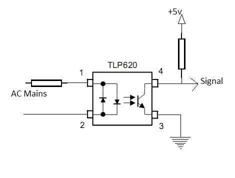
87_1289390177.jpg


19_1289390196.jpg


Hope this helps.
Tahmid.

hi tahmid

Wat is the difference between 4n35 and K817 optocouplers. Can i use K817 to turn on BTA16 triac?
 

For driving triac, you shouldn't use optocouplers such as 4N35 or PC817, not that it's impossible. Look into using opto-triacs like MOC3021, MOC3041, etc.

Depending on your control methodology, select a zero-crossing opto-triac or a non-zero-crossing opto-triac.

Hope this helps.
Tahmid.
 
  • Like
Reactions: ismu

    ismu

    Points: 2
    Helpful Answer Positive Rating
Hi thamid

in inverter circuit "K817/PC817" optocopler is using for dettecting presense of mains. And but in UPS somebody is using 4n35 to measure ac signal voltage.
So can i use "817" opto instead of 4n35 opto in ups?. i want to get analog signal value as output of 817 with isolated from mains. Can i use 817 for this purpose?
 

In your application, you should be able to substitute PC817 for 4N35. You might need to change the drive resistance to increase the drive current for the PC817. Minimum current transfer ratio of PC817 is 50% whereas that for 4N35 is 100%.

Hope this helps.
Tahmid.
 
  • Like
Reactions: ismu

    ismu

    Points: 2
    Helpful Answer Positive Rating
Thanks thamid
Can you check this picture , from this i[1] as input varieying analog type. But i want to get same analog variation in out put like i[2] . I can heard about 4n35 has this property, But will i get for PK817 has same output like I[2] .i think 817 out put is like i[3] . right? if yes , can i convert to i[2] by redusing i[1]?.
 

Attachments

  • opto.png
    opto.png
    10.3 KB · Views: 90
Last edited:

Status
Not open for further replies.

Similar threads

Part and Inventory Search

Welcome to EDABoard.com

Sponsor

Back
Top