Continue to Site

Welcome to EDAboard.com

Welcome to our site! EDAboard.com is an international Electronics Discussion Forum focused on EDA software, circuits, schematics, books, theory, papers, asic, pld, 8051, DSP, Network, RF, Analog Design, PCB, Service Manuals... and a whole lot more! To participate you need to register. Registration is free. Click here to register now.

Neded help converting selenium rectifiers to diodes

Status
Not open for further replies.

Grey Wulf

Newbie level 3
Joined
Dec 12, 2012
Messages
4
Helped
0
Reputation
0
Reaction score
0
Trophy points
1,281
Activity points
1,310
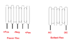
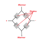
Hello guys, I am new here. I need some help with an old WWII radio power converter, PE-104. Can anyone help me design a replacement to the selenium recs in the picture below. Red arrows show the power rec and ballast rec. What diode would be best? Input power is either 6 or 12 volt. Output voltage is 1.5 on the recs. The 84 and 51 volts are rectified by a syncronous vibrator. IMG_9114.jpg
 

Selenium diodes have a significantly higher voltage drop then silicon diodes (which drop about 0.7V) and that can cause problems with a direct substitution. Once I did a direct substitution in a old B&W tube set for a selenium rectifier used for one of the B+ voltages and the increased voltage caused a distortion in the picture.

A selenium rectifier has about 1V of drop per plate so you can count the number of plates on the rectifier you have to estimate its drop. You would likely want to put a least one silicon diode in series for each plate in the selenium rectifier. Do you have any idea how much current is drawn from the -1.5V or is it just for bias?
 
Last edited:

It is the filament voltage. The 51V is the bias while the 84 is the plate. I dont know the exact ampage draw but the receiver section runs on two D cell batteries. Its being doing so for about 10 hours now. The power converter sits in a compartment that is able to take it or a multivolt/section batery. If it helps, the full radio oull about 20 amps throught an external dyno, but thats for the xmitter as well as the receiver.
 

Brings back memories.... These things used to fail regularly and had to be hit hard with a mallet to get them working again. I think the vibrator contacts used to stick and a little physical assistance was needed to get them moving again!

For the diodes, I would use normal silicon types, when used as replacements it was normal to add a small resistor in series to simulate their high voltage drop.

Brian.
 

Here is some info for those of you more knowledgable than me. The power rec is a 5 stack but is two directional with 2 positive terminals on each end. The ballast rec is a 4 stack. See the diagram.

- - - Updated - - -

What I am trying to figure out is the size of the resistor I would need for each rec.
 

Attachments

  • Rectifier.png
    Rectifier.png
    16.1 KB · Views: 98

Those look to be two selenium junctions in series so the voltage drop wouldn't be much anyway. I would suggest two silicon diodes in series where one selenium one is shown.
Vibrator transformer waveforms are usually horrendously full of spikes so I would use a high voltage diode like a 1N4007 as the silicon replacements.

Brian.
 

I thought this might be a good setup, just to mimick the circuit. See attached pic. The Ballast I thought could be just a single diode sincde it is just a straight ciecuit, but the power rec works off the transformer. I should mention that the positive lugs on the power rec are jumpered together. Would I need any drop down resistors and what would be a good size diode? I think its best to over build than have one burn up.
 

Attachments

  • Diodes.png
    Diodes.png
    13.1 KB · Views: 102

The bridge rectifier (the one you show) can be single diodes of type 1N4007 as their drop isn't too important. In theory, the peak voltage across them is low, probably less than 20V but as I said, vibrator supplies by their nature send square waves into the transformer and that's a recipe for nasty higer voltage spikes. The 1N4007 can withstand 1KV and 1 Amp which is many times higher than the original selenium type.

For tha ballast diode, the forward voltage dropped across it is 1.5V although it would vary quite a bit from one diode to the next. If you use two silicon diodes in series (1N4007 would be OK) it will give about 1.4V which should be in tolerance.

I'm not sure where in the World you are but 1N4007 is one of the cheapest components you can buy and easily available almost everywhere.

Brian.
 

Status
Not open for further replies.

Similar threads

Part and Inventory Search

Welcome to EDABoard.com

Sponsor

Back
Top