Continue to Site

Welcome to EDAboard.com

Welcome to our site! EDAboard.com is an international Electronics Discussion Forum focused on EDA software, circuits, schematics, books, theory, papers, asic, pld, 8051, DSP, Network, RF, Analog Design, PCB, Service Manuals... and a whole lot more! To participate you need to register. Registration is free. Click here to register now.

"NaN" error on power supply schematic.

Status
Not open for further replies.

Paul98

Member level 5
Joined
Sep 7, 2020
Messages
86
Helped
1
Reputation
2
Reaction score
0
Trophy points
6
Activity points
647
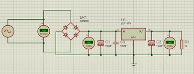
Hello, where is the problem in the circuit in the picture? I replicated the same schematic on LTspice (.asc renamed to .txt) and I have not encountered any kind of problem.Thanks
 

Hi

If LTspice shows no problem, why are you worried?

Usually it´s the OP who tells about the problem...

Klaus

added: Please use a meaningful headline!
 

For some reason I don't see the two attachments I attached in the first message. I link them again in case it is the same for you. The problem is that the regulator on LTspice works well while in the diagram in the image the voltmeters give a reading error "nan".
The title is unclear because I didn't have a chance to edit it once it was sent and I forgot to correct it before publishing it. I can only edit the body of the message.
 

Attachments

  • example.JPG
    example.JPG
    65.8 KB · Views: 256
  • Test.asc.txt
    1.2 KB · Views: 99

Hi,

The attachments are visible.

"nan" means "Not A Number", in other words: not specified.

I see no value at your AC source either....Maybe you did not set it, maybe it´s no shown...

****
What headline text do you want?

Klaus
 

Headline: "nan" error on power supply schematic.

For the "nan" problem accour whem using a rectifier. Bypassing the rectifier stage no problem on working. It's not a program I use often but I don't see anything wrong with it.
 

Attachments

  • 22.JPG
    22.JPG
    69.1 KB · Views: 198

Hi,

then maybe it´s because the AC part is floating. Here some simulators have problems to find the correct operating point.

Try this:
Connect a 10M resistor from AC to GND. (not important which connection)
Then the AC nodes are not floating anymore and the 10M are big enough not to cause errors.

Klaus

Added: Please next time try to give a clear error description in post#1
 

It' apparently a Proteus schematic and thus a Proteus simulator problem. The schematic isn't descriptive, what kind of AC source are you connecting?

I agree that floating sourcce may be the problem.
 

The resistor between AC to ground does not have succes.
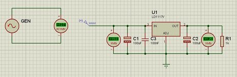
 I had try vsine , alternator and generator/AC . In any case not work. Normally I simulate with LTspice, then sometimes next with proteus and eventually if everything is ok I draw with Kicad. I know that Kicad could do simulation but it is a function that does not seem to me to be fully integrated yet. I hope it will become one in the future because it would also be great for studying.

@FvM can you confirm the problem is in the generators and not in diodes/rectifiers? Can be solved?
 

Can you do with the image on post 3 and 5?
Can you? ... verify whether the 10M resistor is correctly connected?

It´s not very motivating that we have to beg for every little piece of information.


Klaus
 

@KlausST it is not a question of begging. It's just that now I don't have the schematic in front of me to be able to do it. Tomorrow I will post it.
 

Often this is due to a built-in calculation in a "callback" that figures a model property based on instance (symbol) properties. If any of them are not-set or fail to evaluate due to insane values (like a "/0" from a defaulted empty field) then NaN is what you get.

So I'd look real carefully at instance properties, especially ones left empty or given a variable name instead of numeric arguments.
 
Hi,now it seems to be ok although the voltage at the voltage after the diodes should be higher. It also works without putting the resistor on the AC to ground. The strange is that yesterday it didn't even work with resistors. I haven't changed anything in the schematic but just tried to remove the resistors. All the components used have their own SPICE model and the rectifier is made by four 1N4004.
 

Status
Not open for further replies.

Part and Inventory Search

Welcome to EDABoard.com

Sponsor

Back
Top