drwily
Newbie level 4
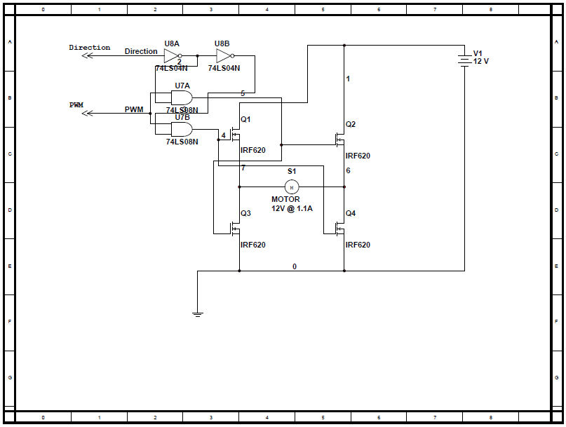
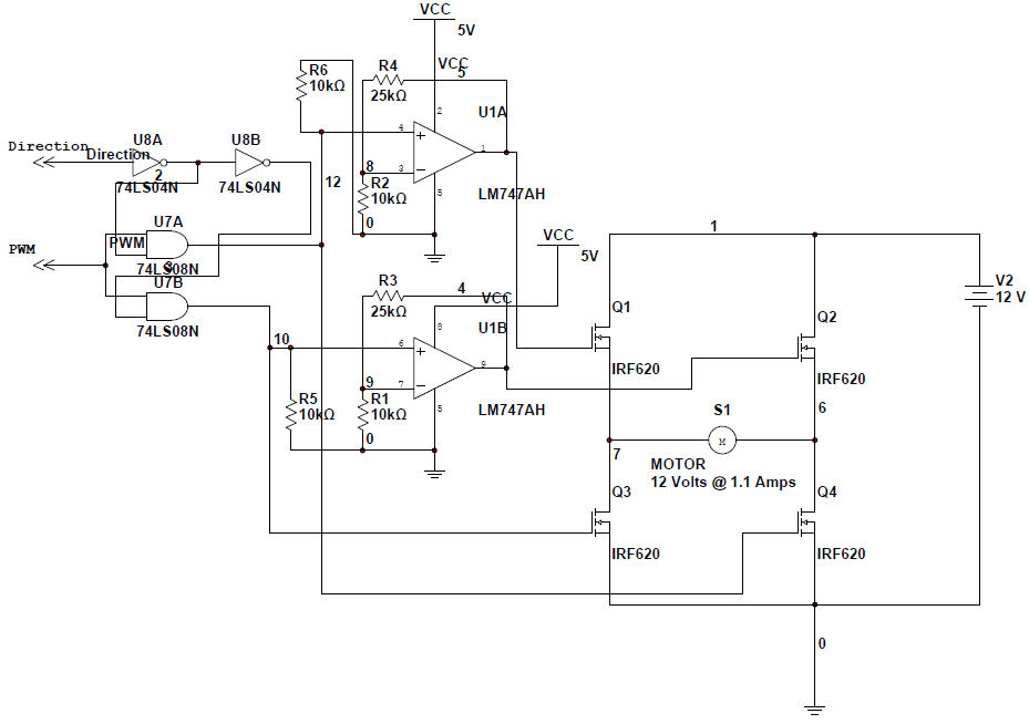
mosfet h bridge
I'm stumped. I can't seem to get this thing working. I only get a humming noise. No motor movement. My o-scope displays a lot of noise when connected to the motor terminals.
I'm stumped. I can't seem to get this thing working. I only get a humming noise. No motor movement. My o-scope displays a lot of noise when connected to the motor terminals.