Continue to Site

Welcome to EDAboard.com

Welcome to our site! EDAboard.com is an international Electronics Discussion Forum focused on EDA software, circuits, schematics, books, theory, papers, asic, pld, 8051, DSP, Network, RF, Analog Design, PCB, Service Manuals... and a whole lot more! To participate you need to register. Registration is free. Click here to register now.

my soundcard oscilloscope probe schematic. plz give suggestions

Status
Not open for further replies.

d@nny

Full Member level 5
Joined
May 28, 2011
Messages
246
Helped
11
Reputation
22
Reaction score
11
Trophy points
1,298
Activity points
3,238
hello!
i am using the following probes for my sound card oscilloscope.
probe.jpg
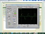
it is giving me the following results from pic16f819 50 hertz oscillator. the frequency counter shows 49 hertz. because it is not complete 50 hertz :p
screen.jpg
but i think the following schematic may improve the input signal and save my sound card from surges.
probes.jpg
is it good or some more suggestions please
 

I don't understand the basic idea. A soundcard has two singled ended stereo channels, but not a differential input. To which terminals of the input plug does your "probe" actually connect? I expect a midrange (several 10K) input impedance for a soundcard, so the purpose of "1 mΩ" (I guess you mean M = Mega rather m = milli) resistors isn't obvious. Do you intend a particular voltage divider ratio? Bypassing it with capacitor creates an additional, possibly unwanted, frequency response and in turn distortion of time domain waveforms.
 

the input is connected with left channel in line in of sound card.
 

the input is connected with left channel in line in of sound card.
Then sound card and probe ground should be directly connected.
 
  • Like
Reactions: d@nny

    d@nny

    Points: 2
    Helpful Answer Positive Rating
i have no voltage divider network as the 1 Mega ohm on both sides drops the voltage and ampere.

---------- Post added at 09:10 ---------- Previous post was at 09:09 ----------

wots about the resistor? 1 mohm is ok or i need to increase it to 2 Megaohm

---------- Post added at 09:10 ---------- Previous post was at 09:10 ----------

i have no voltage divider network as the 1 Mega ohm on both sides drops the voltage and ampere.

---------- Post added at 09:10 ---------- Previous post was at 09:09 ----------

wots about the resistor? 1 mohm is ok or i need to increase it to 2 Megaohm

i have inseted 1M on both sides for ac signal
 

i have no voltage divider network
There is a voltage divider with the unknown sound card input impedance.

When not connecting both grounds, the soundcard will pick up the common mode voltages between both grounds. The result may be very different depending on the computer and circuit power supply connections, but unwanted anyway.
 

should i connect the second channel ground with gound probe. and i should make a voltage divider or not in circuit?
 

A better solution would be with an active circuit like an opamp or an instrumentation amplifier like AD620 so that you can use a high input impedance and have a low output impedance to feed the input card.
Then you can use voltage dividers in the input of the probe or use the gain to be able to view a wider voltage range.

Alex
 

I have been using the sound card as an oscilloscope for some time (with the same software as yours, incidentally), and I find a potential divider of 10:1 to be ideal, as long as your inputs are within 5 volts. The sound card is tolerant of 1 volt p-p, and as your pic circuit would be operating at 5, the divider would safely drop that to 0.5. Values of 10K and 1 K work for me.

Regards,

Anand Dhuru
 

Status
Not open for further replies.

Similar threads

Part and Inventory Search

Welcome to EDABoard.com

Sponsor

Back
Top