mohamis288
Full Member level 3
Hello,
I am simulating moving-average filter in modelsim. some confusing result have been observed and I explain them here.
My moving average filter is 7-tap and my verilog code is represented here:
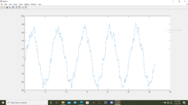
When I simulate this verilog code in modelsim, the result is completely wrong. in fact, we expect our output to be average of last seven input samples. but what we observed was just a 3-sample delayed version of input. in fact, in ideal simulation, modelsim ignore all the multiplier and some of delays. I also synthesized my code in code vision and I observed the synthesized circuit and understood that my observation were correct, i.e., multiplier were not present in my circuit and also input was connected directly to the output by first 3 DFF in between. input also was connected to the last 3 DFF (connected in series) which its output was no connect.
what is the problem do you think?
please give me a point. any help would be appreciated.
I am simulating moving-average filter in modelsim. some confusing result have been observed and I explain them here.
My moving average filter is 7-tap and my verilog code is represented here:
Code:
`timescale 1ms / 1ps

// Module Name: FIR_Filter


module movingAverage_Filter(clk, reset, my_data_in, my_data_out);

parameter N = 8;

input clk, reset;
input [N-1:0] my_data_in;
output reg [N-1:0] my_data_out;

// coefficients defination
// Moving Average Filter, 7th order

//wire [7:0] b0 = 0_0001010;
//wire [7:0] b1 = 0_0010000;
//wire [7:0] b2 = 0_0101000;
//wire [7:0] b3 = 0_1000000;
//wire [7:0] b4 = 0_0101000;
//wire [7:0] b5 = 0_0010000;
//wire [7:0] b6 = 0_0001010;

wire [7:0] b0 = 0.078125;
wire [7:0] b1 = 0.125;
wire [7:0] b2 = 0.3125;
wire [7:0] b3 = 0.5;
wire [7:0] b4 = 0.3125;
wire [7:0] b5 = 0.125;
wire [7:0] b6 = 0.078125;


wire [N-1:0] x1, x2, x3, x4, x5, x6;

// Create delays i.e x[n-1], x[n-2], .. x[n-N]
// Instantiate D Flip Flops
DFF DFF0(clk, reset, my_data_in, x1); // x[n-1]
DFF DFF1(clk, reset, x1, x2);      // x[x[n-2]]
DFF DFF2(clk, reset, x2, x3);      // x[n-3]
DFF DFF3(clk, reset, x3, x4);
DFF DFF4(clk, reset, x4, x5);
DFF DFF5(clk, reset, x5, x6);


//  Multitiplication
wire [N-1:0] Multi0, Multi1, Multi2, Multi3, Multi4, Multi5, Multi6;
assign Multi0 = my_data_in * b0;
assign Multi1 = x1 * b1;
assign Multi2 = x2 * b2;
assign Multi3 = x3 * b3;
assign Multi4 = x4 * b4;
assign Multi5 = x5 * b5;
assign Multi6 = x6 * b6;


// Addition operation
wire [N-1:0] Add_final_value;
assign Add_final_value = Multi0 + Multi1 + Multi2 + Multi3 + Multi4 + Multi5 + Multi6;

// Final calculation to output
always@(posedge clk)
my_data_out <= Add_final_value;

endmodule


module DFF(clk, reset, my_data_in, data_delayed);
parameter N = 8;
input clk, reset;
input [N-1:0] my_data_in;
output reg [N-1:0] data_delayed;

always@(posedge clk)
begin
    if (reset)
    data_delayed <= 0;
    else
    data_delayed <= my_data_in;

end

endmodule
When I simulate this verilog code in modelsim, the result is completely wrong. in fact, we expect our output to be average of last seven input samples. but what we observed was just a 3-sample delayed version of input. in fact, in ideal simulation, modelsim ignore all the multiplier and some of delays. I also synthesized my code in code vision and I observed the synthesized circuit and understood that my observation were correct, i.e., multiplier were not present in my circuit and also input was connected directly to the output by first 3 DFF in between. input also was connected to the last 3 DFF (connected in series) which its output was no connect.
what is the problem do you think?
--- Updated ---
please give me a point. any help would be appreciated.
Last edited: