Continue to Site

Welcome to EDAboard.com

Welcome to our site! EDAboard.com is an international Electronics Discussion Forum focused on EDA software, circuits, schematics, books, theory, papers, asic, pld, 8051, DSP, Network, RF, Analog Design, PCB, Service Manuals... and a whole lot more! To participate you need to register. Registration is free. Click here to register now.

[SOLVED] MY LCD 2 x16 not working

Status
Not open for further replies.

macobt2011

Newbie level 5
Joined
May 5, 2011
Messages
10
Helped
0
Reputation
0
Reaction score
0
Trophy points
1,281
Activity points
1,356
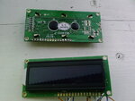
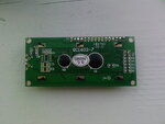
I have 3 of this lcd 2 x 16 and all of them not working I dont know where is problem,I have built several circuits who are working with lcd 2x16 lcd and on all the circuits the display is blank,I try on 3 new display and same problem nothing is shown:(.below are atached the lcd displays.
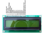
 

Attachments

  • Photo-0113.jpg
    Photo-0113.jpg
    538.5 KB · Views: 89
  • Photo-0114.jpg
    Photo-0114.jpg
    494.3 KB · Views: 82

Can you show how your schematic?
You connect 4bit mode or 8bit mode?
 

from your images in the first post it is quite clear that you haven't grounded D0,D1,D2,D3 as you should for 4 bit operation (since there is no solder on them)

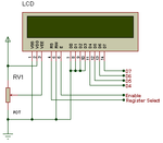
The correct connection for 4bit is like
lcd.png

Alex

P.S. yes now I see that you have them unconnected in the schematic of post #3 too, it can't work this way
 
Still nothing,I grounded D0,D1,D2,D3 and blank display.
How to test the lcd display some schematic,with some microcontroller,i got pic16f84,pic16f628.
 

have u adjusted the contrast correctly may be display is there (if u configure ur lcd in ur programme correctly) but due to low contrast u r unable to see anything?
 
I try with two difrent circuits and firmware is ok for both.
 

The schematic in post #3 if fine but make sure that the port pins are properly defined and that the correct LCD pins are connected to them.
If this doesn't solve the problem then it must be a problem in the LCD library of your code

Alex
 

post your code it may have problem...

---------- Post added at 22:13 ---------- Previous post was at 22:12 ----------

what is your supply voltage. Check if lcd is getting supply... add pull up resistors to port pins too.......
 

Note:I built several difrent projects and on all of them the displays is not working,I have try with 3 difrent lcd displays and all of them are the same type.
This project that I post up in this thread its working project nothing is wrong with code.
The problem is somewhere in displays cant find where?
 

is it completely blank or you get black box.. is there 16 pins or 14 pins in lcd??

---------- Post added at 22:23 ---------- Previous post was at 22:21 ----------

have you connected pin15 to vcc and pin 16 to ground???
 

The display is blank just the led is turn on,the display is with 16 pins.
Also I try to adjust the contrast with trimmer but nothing.
Yes I connect the pin 16 to - and 15 to + 5v
 

I know that a pins 15 and 16 are backlight.I am gona eat the displays:evil:
 

if you can't change the contrast then there is something wrong with the power supply pins and the pot, this is irrelevant to any of the other connections and should work even if the other line are not connected, double check the connection as in the schematic I have posted
 

i have made the same error first time and my contrast connections were wrong. it is not possible that u adjust pot but lcd is blank with only led.
 

Do you see the contrast changing when you adjust the pot?
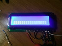
You should see the boxes fading when you change the setting
 

Status
Not open for further replies.

Part and Inventory Search

Welcome to EDABoard.com

Sponsor

Back
Top