Continue to Site

Welcome to EDAboard.com

Welcome to our site! EDAboard.com is an international Electronics Discussion Forum focused on EDA software, circuits, schematics, books, theory, papers, asic, pld, 8051, DSP, Network, RF, Analog Design, PCB, Service Manuals... and a whole lot more! To participate you need to register. Registration is free. Click here to register now.

My first AVR Programmer does not recognise My first AVR LED demo Board

Status
Not open for further replies.

PA3040

Advanced Member level 3
Joined
Aug 1, 2011
Messages
883
Helped
43
Reputation
88
Reaction score
43
Trophy points
1,308
Visit site
Activity points
6,936
Dear All,
My first AVR programmer and LED Memo board dose not recognize the my ATMEGA 32A MCU

Programmer

AVR PROGRAMMER.JPG

LED Demo board

AVR DEMO1.JPG


Programmer schismatics

https://electronics-diy.com/avr_programmer.php

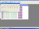
SOFTWARE - PonyProg2000

Hardware test without connecting demo board --working
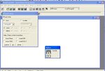
avr hardware.JPG

Problems,
I did not see MCU auto detection from this software like (PIC800- JDM Programmer for PIC)
Device reading continue even device disconnected from the programmer

Please help
Thanks in advance
 
Last edited:

Dear alex,
Thanks for reply

I selected MCU manually but result is same

try to read the m32 fuses?

Can you please explain more

please advice
Thanks in advance
 

The programmers can read/write the mcu fuses, read/write eeprom, read/write flash.

I haven't used ponyprog but there should be a function to read the microcontroller fuses, if you can then the communication is OK
 
  • Like
Reactions: PA3040

    PA3040

    Points: 2
    Helpful Answer Positive Rating
Hi
Yes I did it, but problem is remaining unchanged

avr fuse.JPG

Can I have the simile free download software
Please help
Thanks in advance
 

I'm not sure I understand the problem.
I originally thought you were not able to communicate with the mcu and program it
My first AVR programmer and LED Memo board dose not recognize the my ATMEGA 32A MCU

So the only problem is that the mcu model is not automatically recognized but if you set the model manually everything is fine?

- - - Updated - - -

I think the read fuses are wrong, I suppose that is what you mean so the communication is not proper
 
  • Like
Reactions: PA3040

    PA3040

    Points: 2
    Helpful Answer Positive Rating
I am also still suspect that the MCU recognize by software


Please help
Thanks in advance
 

I think I have traced the problem, you have a high load in the ISP pins so the programmer can't actually drive it , it has to drive the leds in addition to the pins but it is not powerful enough (rarely programmers can do that).
As soon as you unsolder the led resistances from the ISP pins everything will work

- - - Updated - - -

The alternative is to make a programming socket (need supply and crystal) and place the mcu there each time you want to program it and then place it back on the board
 
  • Like
Reactions: PA3040

    PA3040

    Points: 2
    Helpful Answer Positive Rating
Dear Alex,

As per the attached picture , is it necessary to supply external +5v or +5V supply by the serial connector

avrpro.JPG

you have a high load in the ISP pins so the programmer can't actually drive it

Dear Alex I am sorry, I can not mention that, still I am not solder the LED's and Resistors to board
first i need is verify the communication between MCU and software


Please advice
Thanks in advance
 
Last edited:

Yes, you have to power the mcu board and when you connect the board with the programmer plug you will supply the programmer too.
BC549 can't provide the reser signal if the collector resistor isn't connected to Vcc

- - - Updated - - -

There is no way this can work unless you remove the load or remove the mcu from the board.
The data lines in the programmer have 4k7 resistors there is no way they can drive the leds so they will never be able to change the state of the ISP pins
 
  • Like
Reactions: PA3040

    PA3040

    Points: 2
    Helpful Answer Positive Rating
Can I have the link to download alternative software instead of ponyProg

Dear Alex I am sorry, I can not mention that, still I am not solder the LED's and Resistors to board
first i need is verify the communication between MCU and software

Thanks
 

I don't know which softwares can work with your programmer and the programmer page only mentions ponyprog so I can't suggest others.

So the leds are not connected.
Did you apply power supply to the board and programmer and it still doesn't work?
 
  • Like
Reactions: PA3040

    PA3040

    Points: 2
    Helpful Answer Positive Rating
Dear Alex,

Thanks for reply and advice

Did you apply power supply to the board and programmer and it still doesn't work?

Yes I apply power both board and programmer still not working
I dabble checked connection and connectivity and everything is fine
Please advice
 

Are you sure that you apply 5v to the programmer?
It can't be transfered through the programming cable because the Vcc pad in the board side plug is not connected anywhere.
Did you use external cable to give the power supply to the programmer?

I'm not sure what other solution to suggest, I have only used AVRISP MKII, USBASP and TINY USB and a STK200 (LPT port) and all worked fine.

- - - Updated - - -

Have you ever programmed the chip or is it with factory settings?
If you have programmed it maybe you have used wrong clock source fuse settings.
 
  • Like
Reactions: PA3040

    PA3040

    Points: 2
    Helpful Answer Positive Rating
Dear Alex,
.
Thanks for reply.
I never programed the AVR chips, still testing with programmer. I am using new ATMEGA 32A, I think it has factory setting

If you have programmed it maybe you have used wrong clock source fuse settings.

Does it effect the clock source and fuse setting for AVR serial programmer to recognize the MCU?

I think PIC dose not have such features that AVR have? Am I correct?
Please help
 
Last edited:

I don't use PIC so I don't know much about them.

The m32 default clock source is the internal RC 1MHz , in order to change it you have to specifically write new fuse values, writing the flash or any read doesn't effect them.

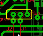
I noticed the following in your board, I suppose it is intended for jumpers
Snap1.gif

The right side is the regulator output, the middle goes to mega16 supplies and the left pad goes to the programmer plug.
In order for this to work you have to connect all three pads together using jumpers so that the regulator supply goes to both the programmer and mega16 , have you done that?
 
  • Like
Reactions: PA3040

    PA3040

    Points: 2
    Helpful Answer Positive Rating
Dear Alex
Thanks for the big help from the beginning
As you pointed out the picture. I done it and problem remaining same

Later I checked the programmer PCB base on your following sentence
I'm not sure what other solution to suggest, I have only used AVRISP MKII, USBASP and TINY USB and a STK200 (LPT port) and all worked fine.

AVR PROGRAMMER.JPG
I found my wrong design by mistake
In DB9 connector I read wrong direction
I corrected it now it is working well

Corrected design
avr corrected.JPG

Dear alex,
Can we able to modify the programmer to get +5v from the serial port instead of supplying from external source
Please advice
 
Last edited:

There is no 5v available in the serial port, use the voltage from the boards.
You can either change the wiring of the plugs or modify the tracks
 
  • Like
Reactions: PA3040

    PA3040

    Points: 2
    Helpful Answer Positive Rating
Dear alexan_e

Please let me know that the programming of AVR is same as Atmel 89c52 because i can program in C langauge.
 

Status
Not open for further replies.

Part and Inventory Search

Welcome to EDABoard.com

Sponsor

Back
Top