Continue to Site

Welcome to EDAboard.com

Welcome to our site! EDAboard.com is an international Electronics Discussion Forum focused on EDA software, circuits, schematics, books, theory, papers, asic, pld, 8051, DSP, Network, RF, Analog Design, PCB, Service Manuals... and a whole lot more! To participate you need to register. Registration is free. Click here to register now.

Multiplexing 18 IR Receive Diodes

Status
Not open for further replies.

djnik1362

Full Member level 2
Joined
Aug 9, 2010
Messages
136
Helped
1
Reputation
2
Reaction score
1
Trophy points
1,298
Location
IRAN
Activity points
2,374
Hi Everyone

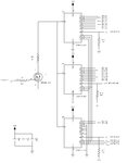
I design a circuit to multiplex 18 IR Receiver Diodes to a Driver Circuit as depict in following picture :


irrx_drv.JPG


Despite the wrong connection for MUX Enable (must be GND to be enabled) there is huge transient
during MUX switching (about 4ms) .

On the other side of the circuit each diode connected to +5V at K and it's A is connected to MUXes.

Do you have any suggestion for this problem or whole circuit ? (May be i do something wrong in Driver Circuit too)

Thanks for your help.
 

Hi,

it would be helpful to see a scope picture...

C131 and R116 is a high pass filter with tau = 0.5ms. you could lower R116 to be faster.
Maybe extra delay is caused by saturated input stage of OPAMP. You could try two anti-serial 2.1V zeners across R119 to optimize.
R75 is useless.

Supply voltage of OPAMP and comparator is not shown. Also all VCC bypass and bulk capacitors are missing.

Klaus
 
I believe you'll understand why the circuit is behaving bad if you think a liitle bit about it's operation. Each photodiode will discharge while disconnected and has to be charged to 5V first when it's ctivated, causing the observed transient.

The lessest thing would be to place an individual bias resistor for each photodiode, better individual coupling capacitors to allow for different DC operation point of each diode if required.

There will be still considerable crosstalk form switching signal, but it may work for sufficient strong photodiode signals.
 
The over all design seems to be wrong to me. As the output stage is a schmidt trigger, then the infra red signal must be digital. So you have 18 diodes whose OFF and ON resistance must be matched, so that after Muxing and multiplied by 15 do not overload the schmidt.
The 4mS is this when you switch slowly from diode to diode, say every 100mS, or is it when you switch from an ON diode to an OFF diode.
Frank
 
Are you operating the diodes in photovoltaic mode?

I'm with FvM on this one. Each diode must be individually terminated with its own bias resistor.
 
Hi,

it would be helpful to see a scope picture...

C131 and R116 is a high pass filter with tau = 0.5ms. you could lower R116 to be faster.
Maybe extra delay is caused by saturated input stage of OPAMP. You could try two anti-serial 2.1V zeners across R119 to optimize.
R75 is useless.

Supply voltage of OPAMP and comparator is not shown. Also all VCC bypass and bulk capacitors are missing.

Klaus

thanks for your suggestions . I bypassed opamp and comparator with two CAPs but not shown in picture .
I put R75 for reducing noise in comparator output (Like Schmitt Trigger).

- - - Updated - - -

I believe you'll understand why the circuit is behaving bad if you think a liitle bit about it's operation. Each photodiode will discharge while disconnected and has to be charged to 5V first when it's ctivated, causing the observed transient.

The lessest thing would be to place an individual bias resistor for each photodiode, better individual coupling capacitors to allow for different DC operation point of each diode if required.

There will be still considerable crosstalk form switching signal, but it may work for sufficient strong photodiode signals.

Thanks . Very useful . So you suggest i put a decoupling cap on each Diode's Cathode and use a bias like R115 .
But i guess maybe there will be a problem when using a bias resistor for each individual diode because diodes have distance
from driver circuit and i think maybe it is better to multiplex diode's current rather than voltage .
I don't know !

- - - Updated - - -

The over all design seems to be wrong to me. As the output stage is a schmidt trigger, then the infra red signal must be digital. So you have 18 diodes whose OFF and ON resistance must be matched, so that after Muxing and multiplied by 15 do not overload the schmidt.
The 4mS is this when you switch slowly from diode to diode, say every 100mS, or is it when you switch from an ON diode to an OFF diode.
Frank

Thanks for your comment . what do you suggest ?

- - - Updated - - -

Are you operating the diodes in photovoltaic mode?

I'm with FvM on this one. Each diode must be individually terminated with its own bias resistor.

Diodes are put on a backplane PCB board and connected to driver board with a 40cm flat cable.
I don't know what photovoltaic mode is but diodes were biased with +5V at Cathode and their Anode connected to MUXes.
Don't you think with biasing each diode the performance will be degraded because i guess
with this distance maybe it is better to multiplex diode current rather than diode voltage .

- - - Updated - - -

Because you guys were so generous in giving me information about my design
i decided to bother you a little more and ask you to give me your suggestions about
my Transmitter Circuit too. So there is my transmitter circuit :
IRTX_DRV.JPG

Except the wrong pull-down in Multiplexer's Enable what do you think about this circuit ?
Is there anything wrong ? I must drive 18 IR Transmitter diodes . I Put 18 Transmitter diodes in
a backplane PCB board and connected them to the driver board with a 40 cm Flat Cable .

Thanks for your support.
 

from driver circuit and i think maybe it is better to multiplex diode's current rather than voltage. I don't know !

Sounds like you don't yet understand the problems that are brought up by "multiplexing current" in your circuit. It involves 5 V voltage swing at the anode because the photo diodes are discharged between scan intervals. Respectively diodes and circuit capacitances have to be reacharged each time when reading a diode. Multiplexing current in a reasonable way would require a short switch at each transistor.

I also don't see which "distance" problem with voltage multiplexing you're referring to. Actually it's hard to make the circuit operating worse than it's now.
 
Hi,

I put R75 for reducing noise in comparator output (Like Schmitt Trigger).
For this you need an extra input resistor.

About your photodiodes.... Do they need biasing? Try to operate them with 0V.

Klaus
 
About your photodiodes.... Do they need biasing? Try to operate them with 0V.
Current switching with zero bias will in fact involve less voltage swing, but still about 0.5 V between open and short circuit with respective transient currents. The solution may be feasible if photodiode and wiring capacitance is relative small compared to the common input node.
 
Hi,

Yes.

it also depends on multiplexing frequency. If it changes every minute, then the 4ms won´t be a problem.
If he likes to switch every 1ms, then it surely is a problem.

I little more info about the whole application could help to understand the function and to give better advice.

Klaus
 
I understand now what you mean . thanks .
The switching frequency is about 1800 Hz . So with biasing each diode
can i reach to this frequency ?
Where i put these biasing resistors ,
on driver board or near the diodes ?

Did you see my transmitter circuit ? this circuit works fine
but i am a little confusing about floating TX diode after switch (Multiplexer path) is off.
Do i need to bias TX diodes too for example with a 100K resistor so
when the TX diode is disconnected from Multiplexer then it's current
can drain through this resistor ?

View attachment 118166

Except the wrong pull-down in Multiplexer's Enable what do you think about this circuit ?
Is there anything wrong ? I must drive 18 IR Transmitter diodes . I Put 18 Transmitter diodes in
a backplane PCB board and connected them to the driver board with a 40 cm Flat Cable .


- - - Updated - - -

Hi,

Yes.

it also depends on multiplexing frequency. If it changes every minute, then the 4ms won´t be a problem.
If he likes to switch every 1ms, then it surely is a problem.

I little more info about the whole application could help to understand the function and to give better advice.

Klaus

The switching frequency is about 1800 Hz .

- - - Updated - - -

Hi,


For this you need an extra input resistor.

About your photodiodes.... Do they need biasing? Try to operate them with 0V.

Klaus

Can you explain why i need an extra resistor and where i must put it ?
Yes, as i mentioned i have biased them with +5V at Cathode and their Anodes
are connected to Multiplexer but we find out that this scheme is not
good and i must bias each diode separately .
 

Hi,

Schmitt trigger: more exactely: Comparator with hysteresis.
For the positive feedback to work you need a defined input impedance. Read on how to generate a defined hysteresis.
--> https://en.wikipedia.org/wiki/Comparator_applications

Bias:
Try to connect all cathodes to 0V (instead of 5V). It depends on the diodes, but it should work. Maybe worth a try. The setup time should be faster.

But the independent biasing method should be even faster.

Klaus
 
When the photodiode is not selected and thus essentially operating in photovoltaic mode.
When the switch is closed and the photodiode operates in photocurrent mode, there will be a transition time where you have to discharge the stray capacitance charged during the photovoltaic period.

To make a long short: You cannot change photo modes without having a transient. I understand your concern that current mode could be more noise immune, but your switching mechanism does not work. At least not at the sampling speed you want.
 
Status
Not open for further replies.

Similar threads

Part and Inventory Search

Welcome to EDABoard.com

Sponsor

Back
Top