Continue to Site

Welcome to EDAboard.com

Welcome to our site! EDAboard.com is an international Electronics Discussion Forum focused on EDA software, circuits, schematics, books, theory, papers, asic, pld, 8051, DSP, Network, RF, Analog Design, PCB, Service Manuals... and a whole lot more! To participate you need to register. Registration is free. Click here to register now.

Multiple voltage to microcontroller design.

Status
Not open for further replies.

maniac84

Full Member level 6
Joined
Mar 4, 2012
Messages
337
Helped
1
Reputation
2
Reaction score
1
Trophy points
1,298
Activity points
3,661
Hi guys, I want to build a circuit of production counter display where when there is an output from a machine, it Wil produce a count signal n my display Wil start increment one.

The machines are using PLC and different machine will produce different voltage of count signal. Some are 5vdc, 12vdc n 24vdc.

For my display, I use a pic controller which using 5vdc.

So, is there any component which can convert a large range of voltage, in my case 5vdc-24vdc to 5vdc where my pic controller can accept as input? Or is there other way to do this circuit?
 

It's very simple, use a pair of resistors to diVide the voltage down. One in series with the voltage, the other from the measurement side to ground. For added safety, it's wise to connect a Zener diode across the measurment side to limit any over voltage conditions so they don't cause damage.

Google for 'potential divider' for a full explanation and how to calculate the values.

Brian.
 

If the LOW voltage for all the signals (with 5V, 12V and 24V) is less than 1V then simple resistor divider or a zener diode solution would work effectively. If the LOW voltages are more than that then PIC might indicate some faulty counts. So you may have to consider using comparators for 12V, 24V signals if required. The output of the comparator then can be converted to 5V Logic level and fed to microcontroller circuit.
 

If the LOW voltage for all the signals (with 5V, 12V and 24V) is less than 1V then simple resistor divider or a zener diode solution would work effectively. If the LOW voltages are more than that then PIC might indicate some faulty counts. So you may have to consider using comparators for 12V, 24V signals if required. The output of the comparator then can be converted to 5V Logic level and fed to microcontroller circuit.
What do u mean by Low voltage?
Can explain more?
 

What Ravindragudi means is the PLC produces two levels of voltage out, a high voltage (5V, 12V, 24V) and a low voltage which hopefully is close to zero. Scaling the high voltage down to your 5V limit is easy with the resistors as I mentioned earlier but if the low voltage is not zero but some voltage higher than zero, even after scaling it might be too high for the PIC to recognize as logic low.

Examples:
PLC produces 24V high and 0V low, scaling reduces that to 5V and 0V respectively and the PIC is happy.
PLC produces 24V high and 15V low, scaling reduces that to 5V and 3.12V respectively and the PIC sees both as being logic high. 3.12V is above the '0' threshold.

So if the low output really is zero or close to it there is no problem. If it isn't the solution is to use comparators to detect if the PLC output is above or below a voltage somewhere in the middle of it's high and low range. The comparator output would be a 5V logic signal the PIC would recognize.

Brian.
 

There should be a comparator that works with nominal uC voltage ( 5V ) for each PLC output.Comparators can be programmed in according with output levels-for instance- 20V for 24V output, 10V for 12V output so on..
Finally the comparator outputs will always be 0 or 5V when the signals levels' exceed the programmed value..
 

What Ravindragudi means is the PLC produces two levels of voltage out, a high voltage (5V, 12V, 24V) and a low voltage which hopefully is close to zero. Scaling the high voltage down to your 5V limit is easy with the resistors as I mentioned earlier but if the low voltage is not zero but some voltage higher than zero, even after scaling it might be too high for the PIC to recognize as logic low.

Examples:
PLC produces 24V high and 0V low, scaling reduces that to 5V and 0V respectively and the PIC is happy.
PLC produces 24V high and 15V low, scaling reduces that to 5V and 3.12V respectively and the PIC sees both as being logic high. 3.12V is above the '0' threshold.

So if the low output really is zero or close to it there is no problem. If it isn't the solution is to use comparators to detect if the PLC output is above or below a voltage somewhere in the middle of it's high and low range. The comparator output would be a 5V logic signal the PIC would recognize.

Brian.

Great example! Now I understand.. thanks!

- - - Updated - - -

There should be a comparator that works with nominal uC voltage ( 5V ) for each PLC output.Comparators can be programmed in according with output levels-for instance- 20V for 24V output, 10V for 12V output so on..
Finally the comparator outputs will always be 0 or 5V when the signals levels' exceed the programmed value..

U mentioned comparator can be programmed? Programmed by what? The PLC or my pic? Can explain more?

How do we build a comparator? Is it by external components? Or we programmed it?
 
Last edited:

U mentioned comparator can be programmed? Programmed by what? The PLC or my pic? Can explain more?

How do we build a comparator? Is it by external components? Or we programmed it?
I talk about simple comparator.They have 2 inputs, one of them is reference input other one is simple input.If input level is higher than reference voltage comparator output rises to Vdd, otherwise is settled to zero.There are tons of comparators in the market, if your search a bit, you'll find many IC circuits...
 

I talk about simple comparator.They have 2 inputs, one of them is reference input other one is simple input.If input level is higher than reference voltage comparator output rises to Vdd, otherwise is settled to zero.There are tons of comparators in the market, if your search a bit, you'll find many IC circuits...

I see. Thanks!
Then do we need to scale down again to 5v using divider after the comparator?
Or the comparator Wil straightaway produce a 5v for high to my pic?
 

Many comparators have 'open collector' or 'open drain' outputs, which means they can pull any external voltage down to zero but not supply a voltage of their own. Consequently, you can externally pull the output up to whatever voltage you like as long as it is within the comparators operating range. If you pull it up to 5V with a resistor it will give a 5V/0V output, if you pulled it up to 12V it would give a 12V/0V output and so on.

You can also use a comparator that gives 5V out directly but then you have to scale the input voltages (reference and the one you are comparing it with) as most devices will not allow their input voltages to go above their supply voltage.

You can make the comparator 'programmable', the method is to generate your own reference voltage using another circuit. It will then tell you if the input is above or below the voltage you generated.

Brian.
 

From u guys opinions, is it that I have to build 3 circuits to detect the signal for different PLC? One circuit for PLC with 5v signal,one circuit for PLC with 12v signal and one for PLC with 24v dignal.
 

You need one comparator for each voltage you are monitoring. You would use different thresholds on each so you have no choice.
However, if you want to monitor them as one signal, because open collector/open drain comparators do not source current there is no danger of one feeding into another so you can join all the outputs together. That would give you a single signal that said, for example, that all the outputs were high simultaneously.

Brian.
 

Ok thanks.
Let's talk about AC signal. If the PLC is coming out with an AC 100v signal, how do we convert to 5vDC so that my pic can detect it?
 

It depends on the reacton time you need. Being AC, half the time it will be the wrong polarity for the PIC and for some additional time near to the zero crossing point the voltage will be too low to detect with a comparator or resistive divider.

You can overcome the polarity problem with a bridge rectifier, basically using diodes to steer the voltage so it's polarity is the same at the output regardless of what it is at the input.

Various options are then available, the simplest being to follow the bridge with a small capacitor and resistor in parallel. The capacitor would charge to a voltage near the peak of the 100V AC (about 140V) and the resistor would allow it to discharge fairly quickly when the AC was turned off. This method allows you to use the potential divider or comparator methods as before. The drawback to this method is the slow reaction time. It takes a relatively long time for the capacitor to discharge (several 10s of mS), you can speed it up by leaking more away through a lower value resistor but that also increases the 'ripple' (unsteadiness in the DC) which may or may not be a problem depending on its severity and comparator 'trip' point.

A faster method is to use the rectified AC without the capacitor and resistor so you are checking pulsing DC. Although it can be faster, the drawback to this method is there will be periods near where the AC polarity changes where the voltage is zero or too low to be recognized. If your PIC samples at that time it will mistakenly think there is no voltage. The fix for that is done in software, you sample the input at least two times with sufficient delay (say > 20% of one AC cycle length) and if either sample is high you assume voltage is there, if both are low you assume it isn't.

Bear in mind that if your AC is not isolated from incoming 'wall socket' power, you may need an additional safety barrier between the AC and PIC. It is fairly easy and cheap to do if you use opto-isolators, let me know if you need advice on how to use them.

Brian.
 

Thanks for the comment.
Back to the DC type of voltage from the PLC. Assume the PLC produce 0V as low voltage. May I ask, can we straightaway use a opto-coupler or opto-isolator? Opto-coupler or opto-isolator can also accept input of higher voltage (for my case 24V and 12V) and output with lower voltage (for my case 5V), right?
 

If the DC outputs for the PLCs are giving out close to 0V for LOW signal then you can use the simple resistor divider or resistor + zener diode solution as mentioned in the beginning. Opto isolators will also do the same job but it will be costing more and will take up more board space.
 

Opto-isolators will always work in DC circuits and are the usual method used in industry because of the way they completely isolate the input and output sides. The input side on almost all types only works on about 1.8V maximum though. There is a real LED at the input side so you have to treat it as such and use a resistor to limit the current allowed to flow through it. The data sheet will tell you the LED voltage and optimum current to use, usually it is in the region of 5mA to 15mA. The resistor value is calculated with:

(supply voltage - LED voltage) / LED current.

On the output side you normally have a transistor working as a switch, it turns on (= closes if it was a mechanical switch) when the LED has current flowing through it so you can either wire it to ground with a pull-up resistor to get an inverted signal or to 5V supply with a pull-down resistor to get a non-inverted signal.

For AC the opto-isolator is more problematic, you have to convert the AC to DC to drive the LED side.

Brian.

So, what you mean is we cannot straightaway connect the PLD signal (for my case: 24Vdc, 12Vdc or 5Vdc) to the opto-isolator? Is it that we have to scale the PLD signal to 1.8Vdc before inputting to the opto-isolator? Is it by using resistors to scale it like we talk before at the beginning of this topic?

- - - Updated - - -

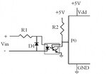
I have done some research regarding the opto-isolator circuit. Based on the below circuit:
img_1224968365_15412_1293141599_mod_393_274.jpg

We just have to adjust the R1 value if we want to use different input voltage Vin.
R1 = (Vin-Vf)/If where Vf=1.2V and If=10mA (values from datasheet of 4N37).

So, for my case, if I'm using 24V as Vin,
R1=(24-1.2)/10m=2280ohm
if 12V, R1=(12-1.2)/10m=1080ohm
if 5V, R1=(5-1.2)/10m=380ohm

Am I correct guys?

Yes thats correct. But select the current into the LED of opto-isolator a little on the higher side. Looking into the DS of 4N37, with power dissipation limit derated @ 60C, the LED can handle power dissipation of upto 70mW. And the max Vf for LED is 1.5V. Having 30% derating on the power dissipation of LED, the LED current can be 70mW X (100% -30%) / 1.5 = 32.66 mA. So select a current of around 30mA. Also there will be variation in the resistance tolerance and Vf, so better select the LED current between 20mA to 30mA. Also check what will be the max output current at the selected LED current level.
 

Instead of 3 opto-isolator circuits, is there a possibilities that we can build one opto-isolator circuit to be able to accept a wide range of input voltage like for my case say from 5V to 24V? Like this I can save more space.
 

Status
Not open for further replies.

Part and Inventory Search

Welcome to EDABoard.com

Sponsor

Back
Top