myle00
Newbie level 5

- Joined
- Sep 30, 2010
- Messages
- 8
- Helped
- 0
- Reputation
- 0
- Reaction score
- 0
- Trophy points
- 1,281
- Location
- U.S.A.
- Activity points
- 1,432
Hi,
I have an ADC board which I'm trying to improve by getting rid of some noise (although it does work fine now). The board from left right is basically an ADC <-> buffer <-> microcontroller <-> FT232R. There are 0.01uF and 10uF caps at each of the chips. Power comes from a 7805 regulator. Using a scope I looked at the power pins noise spectrum in each of the chips. I found the following:
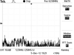
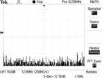
Every pin has 6MHz noise. In addition, some pins (near microcontroller, and ADC digital power pin) also have 25MHz - 50MHz noise. The regulator output pin shows a combination of all the noise (see attached pic). Now, the 25-50MHz noise is suspiciously close to the rise/fall time of the digital signals. In addition, the ADC has a 6MHz crystal, while the uC has a 20MHz crystal. I'm assuming these are the noise sources. Since nothing else runs of this power supply, I'm assuming the supply itself is clean (especially since the noise is absent when everything is powered but there's no acquisition, see second image).
I'm uncertain what do with about this noise. Should I even try to remove it? Some noise will always be present because they all run at high speed. So I'd have to place ferrite beads at each of the Vccs. Alternatively, maybe I just need to protect the ADC analog supply and perhaps prevent the noise from going out of the board to other boards by putting a ferrite bead before the analog pin on the ADC and at the regulator output. What should be my goal be here? Currently, I don't see any major noise in the ADC converted data, but it is effectively filtered by the 1k ADC sampling rate, so maybe the noise doesn't even matter. What is the standard procedure about these things?
Finally, I'm unsure how to pick a bead for these frequencies. At digikey, all are rated with impedance at 100MHz. Should I just pick the one with highest AC impedance and lowest DC impedance at a good price? Do I have to look in each data sheet to see the 6MHz impedance? And how do I know what value to target? Also, the bead effectively increases the output impedance of the regulator, although only at high frequencies isn't this still a bad thing? Finally, at sub MHz frequencies the bead functions as an inductor which effectively amplifies that band's noise so we need more components to fix this are any general rules for this?
Thanks in advance.

