Continue to Site

Welcome to EDAboard.com

Welcome to our site! EDAboard.com is an international Electronics Discussion Forum focused on EDA software, circuits, schematics, books, theory, papers, asic, pld, 8051, DSP, Network, RF, Analog Design, PCB, Service Manuals... and a whole lot more! To participate you need to register. Registration is free. Click here to register now.

MULTIPHASE boost question

Status
Not open for further replies.

bowman1710

Full Member level 3
Joined
Nov 8, 2014
Messages
183
Helped
6
Reputation
12
Reaction score
6
Trophy points
18
Activity points
1,604
Hi guys,

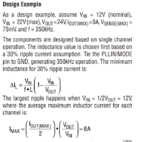
I'm looking at a multiphase boost topology and I'm trying to find some calculations for the inductor design. So far I can only find Linear Tech calculation (attached) and make it out to around 28uH which seems a bit high, but it does say its for single phase application. Anyone have anything or know where I can find information about the value I need?

Thanks in advance
 

Attachments

  • LT datasheet.PNG
    LT datasheet.PNG
    116.1 KB · Views: 60

If you can make all the phases share current equally, then you only take the total output current and divide it by the number of phases.

Thus for a 4-phase circuit delivering 20 amps, the calculation for each inductor would be of 5 amps each.

Having said that, you may notice that I bolded the phrase "If you can make all the phases share current equally". This is far harder than what it seems at first glance, specially during transient conditions, and made it worse by the Right Hand-Plane Zero of a boost converter.
 

around 28uH which seems a bit high, but it does say its for single phase application.

Possible misplaced decimal point? 2.8 uH is a suitable value at 350 kHz.

I'm cheating by using a simulator.

Anyone have anything or know where I can find information about the value I need?

Thanks in advance

I was ready to describe the obvious calculation, based on the LR time constant in the first half of the cycle. This results in an inductor value of 14uH. However as it turns out this is too great a Henry value.

It is due to idiosyncrasies of the boost converter. The second half of the cycle is a different discharge environment from the first half of the cycle. Inductor EMF must overcome a greater voltage at the output node.

Did you use a simulator as a check for your calculations?
 

Thanks Schmitt trigger, I have found some more technical documents supporting this topology. Sorry 28uH was for my application , I haven't used any software to back the calculations that i have done. What software did you use to check this problem BradtheRad?


Status
Not open for further replies.

Similar threads

Part and Inventory Search

Welcome to EDABoard.com

Sponsor

Back
Top