Continue to Site

Welcome to EDAboard.com

Welcome to our site! EDAboard.com is an international Electronics Discussion Forum focused on EDA software, circuits, schematics, books, theory, papers, asic, pld, 8051, DSP, Network, RF, Analog Design, PCB, Service Manuals... and a whole lot more! To participate you need to register. Registration is free. Click here to register now.

[Moved] very LOW brightness In digital voltmeter with ATMEGA8

Status
Not open for further replies.

trm33

Junior Member level 1
Joined
Jan 29, 2009
Messages
15
Helped
1
Reputation
2
Reaction score
1
Trophy points
1,283
Visit site
Activity points
1,391
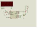
I have designed Digital voltmeter with atmega8 but with only 3 resistors connected to common wires of 3 seven Segments, while all other 8 pins (a-h) are directly interfaced with atmega8. but this shows very low brightness. can we use transistors with all common wires are some other changes are necessary. any suggestion
 
Last edited:

Re: very LOW brightness In digital voltmeter with ATMEGA8

As a first point, you'll want current limiting resistors per segment to get constant segment brightness independent of the number of activated segments. In addition, it's often necessary to use a stronger digit driver than µC output pin, e.g. a transistor.
 
  • Like
Reactions: trm33

    trm33

    Points: 2
    Helpful Answer Positive Rating
Incase if you are using common cathode seven segment display then use individual transistor collector pins connected to the common pins and use transistor as a switch in CE configuration.... And control the switching of transistor using micro-controller such that you can multiplex the segment ..... I suggest you to put your circuit on the forum for better answers....

Good luck
 

Yeah post your circuit here for better replys , How many digits you are using?? If you used more digits in multiplexing you will loose the brightness, increase the ON time for each segment to full up the total period..
 

dvm_CA.jpg

i M USING Common Anode configuaration, circuit is attached
 

Remove the 220Ohm in a,b,c side and put them in 8 outputs... If controller output current doesnt supports, put separate Transistors....
 
  • Like
Reactions: trm33

    trm33

    Points: 2
    Helpful Answer Positive Rating
Status
Not open for further replies.

Similar threads

Part and Inventory Search

Welcome to EDABoard.com

Sponsor

Back
Top