Continue to Site

Welcome to EDAboard.com

Welcome to our site! EDAboard.com is an international Electronics Discussion Forum focused on EDA software, circuits, schematics, books, theory, papers, asic, pld, 8051, DSP, Network, RF, Analog Design, PCB, Service Manuals... and a whole lot more! To participate you need to register. Registration is free. Click here to register now.

[Moved] USB Signal transmitter using LED visible light

Status
Not open for further replies.

diba88

Newbie level 5
Joined
Aug 1, 2013
Messages
10
Helped
0
Reputation
0
Reaction score
0
Trophy points
1
Activity points
78
I am using a composite video to usb converter. From usb i have D+ and D- differential signal coming out. I manually probed the white (D-) and green(D+) wires from my usb cable (I had to slice the wire) to visualize signal outputs using scope.

Now I want to modulate LED light to transmit this digital usb signal (D+/D-) to the receiver. At Receiver end is a PD to decode light to voltage. A USB to composite video converter will be used to display the video at the receiver end. I plan to use arduino UNO board for processing. How do I establish the half duplex system (any code)? Please suggest on voltage level for D+/D-..
 

As first step, you need to understand the USB protocol and physical layer. It's essentially a bidirectional bus. Any attempt to convert USB to optical signal and vice versa needs to separate both data directions and also differential and single ended data.

I'm not sure what your "composite video to usb converter" is. An USB frame grabber? I also don't see how an arduino UNO could connect to a video digitizer, because it's neither an USB host nor able to handle the data rate.
 

I have a video signal coming from a composite video out (we can ignore audio at this point). Products such as EasyCAP can convert such signal to usb differential signal. Arduino can process the incoming signal voltage from usb and modulate the LED accordingly. *This modulation has become the key issue*. Please suggest.

I do not intend to store any video frame. Also the optical signal generated needs to be converted back to voltage which will be directed to a usb-->composite video converter. Please suggest.

On the other hand, if dealing with differential signal is a hassle. How about composite video to VGA converter?? Since VGA signal is single ended, would it make life easier?
 

Your posts are confusing. Do you want to convert baseband video via an optical link to a digitizer as you state in post #3 or do you want to digitize it and send the digital USB data by optical link as stated in post #1?

Converting composite video to LED and back to composite is relatively easy, you can use linear optocouplers or if you are careful, focussed light or laser beams. Sending USB optically is very difficult. The D+ and D- wires are bi-directional so you can't just convert the voltage to light, you have to do it in two directions and have control circuits to decide which direction is active.

I think you might also have difficulty processing video with an Arduino unless it is an extremely fast one!

Brian.
 
  • Like
Reactions: diba88

    diba88

    Points: 2
    Helpful Answer Positive Rating
Hi Brian, thank you for you suggestion. Yes you are right. Initially I wanted to digitize baseband video and send the digital usb data by modulating LEDs. But as you suggested, converting composite video to LED using optocoupler would be relatively easier, could you please provide more info on it? perhaps an example please.

Your posts are confusing. Do you want to convert baseband video via an optical link to a digitizer as you state in post #3 or do you want to digitize it and send the digital USB data by optical link as stated in post #1?

Converting composite video to LED and back to composite is relatively easy, you can use linear optocouplers or if you are careful, focussed light or laser beams. Sending USB optically is very difficult. The D+ and D- wires are bi-directional so you can't just convert the voltage to light, you have to do it in two directions and have control circuits to decide which direction is active.

I think you might also have difficulty processing video with an Arduino unless it is an extremely fast one!

Brian.
 

For video isolation I use Avago's HCPL-4562 devices. The data sheet has application notes and example circuits.

Brian.
 
  • Like
Reactions: diba88

    diba88

    Points: 2
    Helpful Answer Positive Rating
Brian thank you for your reply. It enlightened me in a different route. Instead, I was thinking of a point to point (at least 1 meter apart) led channel.

Is there any way of converting the composite video to TTL? may i can modulate LED using TTL signal. Please suggest. Perhaps give some circuit wiring example so that I can understand the system.

Thank you in advance.
 

Yes, you can digitize the composite video and send the stream by LED light but I warn you, it is quite difficult. What you have to consider is the data rate you need. You have not specified the video source bandwidth so as an example, I'll use 'standard' television definition of 720 x 576 pixels. Each pixel will be set as three 8-bit bytes, one for each of the red, green and blue content of the pixel. If I assume the refresh rate is 50 frames per second, the data rate is 720x576x24x50 = 497,664,000 bits per second (~500MHz) which far exceeds TTL IC speeds! The method used commercially is to compress the video at source but that is a vastly complex task requiring large memories and high speed processing. If you want to try, the standard for digital video is called SDI (Serial Digital Interface) and (I think) runs at 21Mb/s. Google should turn up more information on SDI if you search.

Brian.
 

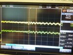
hi guys, i tried different methods to get to a solution regarding the matter above. Eventually i ended up with this attached schematic. I have checked both signals at receiver and transmitter end. peak to peak is around 200-340mv. frequency 8 hz - 600 hz.

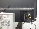
now the problem, when i hook up the rca red(right audio) to my led monitor. no sound is coming out!! what could be the issue here?
 

hi this is the schematic

TRANS_REC_SCHEMATIC.png

this is the oscilloscope observation. the upper signal from transmitter, the lower from receiver end LED. Also the yellow cable on the other picture is the rca audio cable going into the LED TV as a direct line. I am using the CVBS as my RCA Audio cable.

oscilloscope measurement-compressed.jpgRCA AUDIO INPUT-compressed.jpg
 
Last edited:

Status
Not open for further replies.

Part and Inventory Search

Welcome to EDABoard.com

Sponsor

Back
Top