Continue to Site

Welcome to EDAboard.com

Welcome to our site! EDAboard.com is an international Electronics Discussion Forum focused on EDA software, circuits, schematics, books, theory, papers, asic, pld, 8051, DSP, Network, RF, Analog Design, PCB, Service Manuals... and a whole lot more! To participate you need to register. Registration is free. Click here to register now.

[moved] Seek transformerless Power supply circuit design 12V 1A

Status
Not open for further replies.

Prakash.143

Junior Member level 1
Joined
Nov 24, 2015
Messages
16
Helped
0
Reputation
0
Reaction score
0
Trophy points
1
Activity points
165
I want a circuit of Transformer-less power supply circuit diagram whose output is 12V and 1 Amp current.
 

re: Seek transformerless Power supply circuit design 12V 1A

Hi,

What about using a 12V battery?

Klaus
 

re: Seek transformerless Power supply circuit design 12V 1A

I want a circuit of Transformer-less power supply circuit diagram whose output is 12V and 1 Amp current.

From What Power Source?
 

re: Seek transformerless Power supply circuit design 12V 1A

From 230 Voltage AC to 12 V and 1 Amp DC supply
 

Re: Seek transformerless Power supply circuit design 12V 1A

the capacitor will be bigger than a 12v transformer for that amount of current ...
 

Attachments

  • TB008 Transformerless Power Supply.pdf
    57 KB · Views: 131
Last edited:

Re: Seek transformerless Power supply circuit design 12V 1A

From 230 Voltage AC to 12 V and 1 Amp DC supply
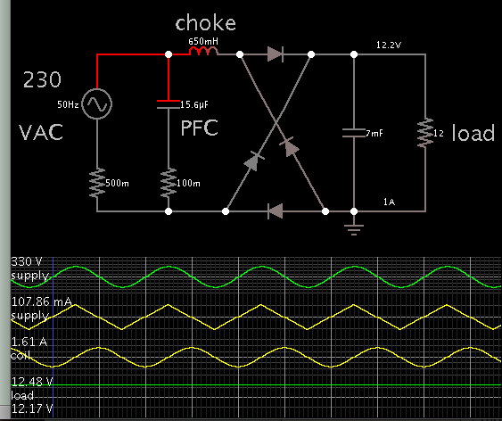
Its not really practical, as the whole of the 1 Amp will need to come from the mains supply.
That is 230VA in to supply only 12 watts out.
These types of supplies are fairly common for very low power, but not for twelve watts.

Cheapest solution would be a "made in China" 12v 1A dc wall pack.
And all of those use a transformer of one type or another.
 

Re: Seek transformerless Power supply circuit design 12V 1A

Although it is possible, it will be impractical from the size of the components. Just the capacitor marked C1 in the diagram will be nearly as big as a switching 220VAC/12VDC @1A wall transformer. These can be purchased for a few dollars.

- - - Updated - - -

Here is another circuit based on a web design.
https://www.electroschematics.com/5499/transformerless-power-supply/
 

Attachments

  • mains_psu1.png
    mains_psu1.png
    39.1 KB · Views: 159
  • mains_psu.png
    mains_psu.png
    27.4 KB · Views: 162
Re: Seek transformerless Power supply circuit design 12V 1A

Yes I agree with above comments, Its very impractical to draw 1Amp from transformerless power supply, although I am also keen to know the way. I don't know whether x rated cap is available for 1Amp supply.
The best way is to open a LED bulb and take out its circuit, as described here:
https://www.instructables.com/id/Transformer-less-12V-power-supply-out-of-LED-bulb/
Also capacitor value for 1Amp, is very very high, according to reactance of cap X= 1/(2*3.14*f*C). We need X=230 for 1Amp current (I = V/X = 230/230 = 1). SO the capacitance goes 72kF!!
I have build a small working prototype using below article, although its not of 1AMp
transformerless-power-supply
 

Re: Seek transformerless Power supply circuit design 12V 1A

**broken link removed** for anyone interested in transformerless power supplies. Especially the part about microchip's infamous TB008 document.

Also capacitor value for 1Amp, is very very high, according to reactance of cap X= 1/(2*3.14*f*C). We need X=230 for 1Amp current (I = V/X = 230/230 = 1). SO the capacitance goes 72kF!!
Not sure how you got that number, it's more like 11.5uF. More realistically you'll be needing more like 15uF, with a 400V rating.
 
@mtwieg I have quickly gone through the above link, but I didn't see any formula or equation for the capacitance calculation. How did you get that figure of 15uF? BTW the Article is informative, will read it detail.

Thanks
 

The calculation is via the capacitive reactance Xc. 1 / (2.pi.f.C)
So think in terms of 50 hz sines, and do V/Xc = I
You know the current that you want, you know V (the mains), then you calculate Xc, then C.
That's the principle
 

Being a series element, the capacitor will drop an AC voltage proportional to Xc AND the current through it. In other words, if you remove the load it will not drop any voltage!

You can design for 1A load but you must ensure something, either the regulation circuit or the device you are powering is actually drawing 1A. If you use a Zener diode it has to be rated > 12W.

Brian.
 

I want a circuit of Transformer-less power supply circuit diagram whose output is 12V and 1 Amp current.

12W and transformerless does not equate to the most reliable lowest cost design unless you choose an offline buck regulator. Using rectified 50Hz with a large C is not cost effective above 5W.
RC must be at least 8x 10ms for 50 Hz for 10% ripple.
 

Just to throw this in the mix...

A choke (inductor) can create reactive drop. It can be called transformerless. It is a counterpart to the capacitive drop. Being reactive rather than resistive, therefore they generate relatively little heat.


A capacitor is needed for power factor correction. To optimize its value, watch mains AC waveforms for V & A. Make them align. Notice that very low current is drawn from mains when power factor is corrected.

Values were adjusted to yield 12V 1A. If you change the load then it puts everything out of balance. This is a problem with inductive drop just as it is with capacitive drop.
 

Status
Not open for further replies.

Similar threads

Part and Inventory Search

Welcome to EDABoard.com

Sponsor

Back
Top